Cutter

A cutting machine and base technology, applied in metal processing and other directions, can solve the problems of operator inconvenience, vibration and noise of the wire saw machine 10, and troubles.

Inactive Publication Date: 2008-08-13
REXON IND CORP LTD
View PDF0 Cites 3 Cited by
  • Summary
  • Abstract
  • Description
  • Claims
  • Application Information

AI Technical Summary

Problems solved by technology

But moving the two cantilever arms 14, 16 up and down will make the wire saw machine

Method used


Image

  • Cutter
  • Cutter
  • Cutter

Examples


Embodiment Construction

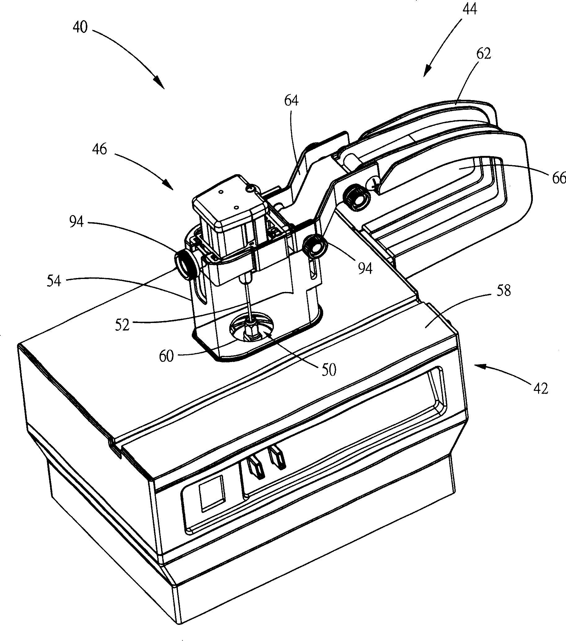
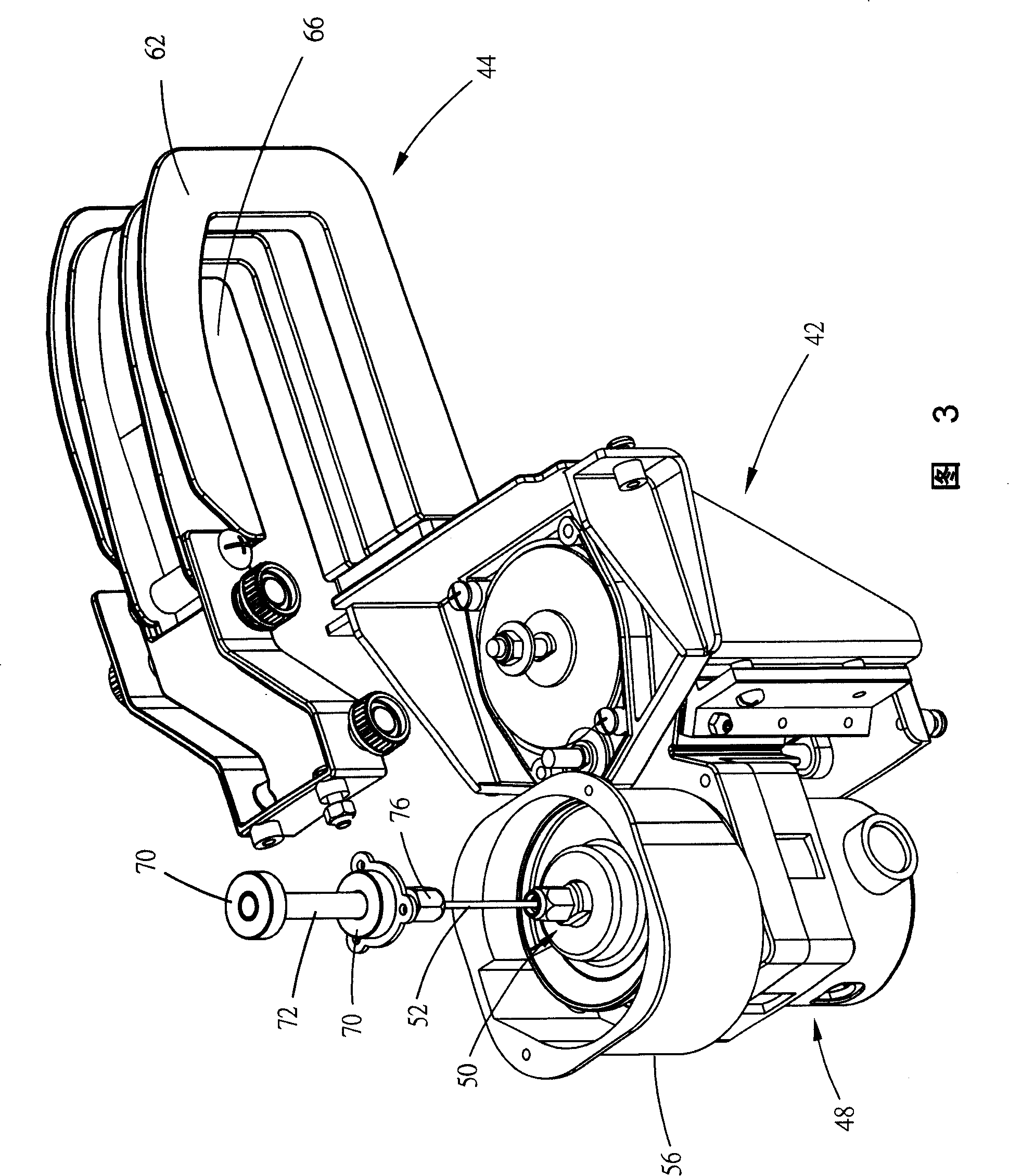
[0013] see figure 2 and Figure 3, figure 2 It is a perspective view of the cutting machine of the present invention, and FIG. 3 is an internal structure diagram of the cutting machine of the present invention. The present invention provides a cutting machine 40. In this embodiment, the cutting machine 40 includes a base 42, an arm 44, a first clamping device 46, a driving device 48, a second clamping device 50, A hob 52 , a limiting member 54 and a dust cover 56 .

[0014] see figure 2 , the top of the base 42 is a working platform 58, the working platform 58 is used to carry a workpiece (not shown) to be cut by the cutting machine 40, and a hole 60 is opened at about its center.

[0015] Support arm 44 has a bow-shaped body 62 and a pivoting part 64, and bow-shaped body 62 forms a throat space 66, can extend wherein when this workpiece changes position on the working platform 58, one end of bow-shaped body 62 is fixed. Connected to one side of the top of the base 42, the ...


PUM


Abstract

The cutting machine in the invention comprises a base, a hob, a driven device, a side arm, a first holding device and a second holding device. The base comprises a work platform, and the object containing frame is used for holding work piece, a hole is set in the platform. The hob goes across the hole and rotates by a central axis to cut the work piece. The driven device comprises a motor which is used to rotate the hob. The side arm is fixed on the base, and the first holding device lining with the side arm holds the end of the hob. The second holding device is set in the inner part of the base to hold the other end of the hob.

Description

technical field [0001] The invention relates to a cutting machine, in particular to a hob-type cutting machine. Background technique [0002] Please refer to FIG. 1 , which is an exploded perspective view of a conventional wire saw machine 10 . The wire saw machine 10 cuts a workpiece (not shown) by moving a saw blade 12 up and down. The mechanism for driving the saw blade 12 includes an upper cantilever 14, a lower cantilever 16, a connecting arm 18, a motor 20, and a drive Wheel 22, a driven wheel 24, a transmission belt 26, a driving member 28 and a driving block 30. The driving wheel 22 is sleeved on a rotating shaft of the motor 20; the transmission belt 26 is wound around the driving wheel 22 and the driven wheel 24; the driving member 28 is locked to an eccentric screw hole 32 of the driven wheel 24; the driving block 30 is fixedly connected to the connecting arm 18 , has a groove 34, which accommodates the driver 28; [0003] When the motor 20 is started, the driv...

Claims


Application Information

Patent Timeline
IPC IPC(8): B26D7/26B26D5/08B26D7/22B26D7/18B26D1/547
Inventor 林昌运
Owner REXON IND CORP LTD
Why Eureka
Try Eureka