Projecting system and its photoconductor tube

A technology of projection system and light pipe, applied in the field of projection system and light pipe, can solve the problems of affecting the uniformity of light, affecting the quality of light output from the light pipe 12, etc., to achieve the effect of ensuring the quality of light output

Inactive Publication Date: 2008-08-13
PRODISC TECH INC
View PDF0 Cites 5 Cited by
  • Summary
  • Abstract
  • Description
  • Claims
  • Application Information

AI Technical Summary

Problems solved by technology

When too much adhesive 122 is used, after curing, the thickness of the adhesive 122 will easily affect the alignment accuracy of the optical components 121, thereby affecting the uniformity of light
In addition, when assembling the light pipe 12, the adhesive 122 may also overflow into the inner surface of the light pipe 12, thereby affecting the light quality of the light pipe 12, which really needs to be improved.

Method used


Image

  • Projecting system and its photoconductor tube
  • Projecting system and its photoconductor tube
  • Projecting system and its photoconductor tube

Examples


Embodiment Construction

[0075] For further elaborating the technical means and effects that the present invention takes for reaching the intended invention purpose, below in conjunction with accompanying drawing and preferred embodiment, to its specific implementation mode, structure, feature and effect of (title) proposed according to the present invention, Details are as follows.

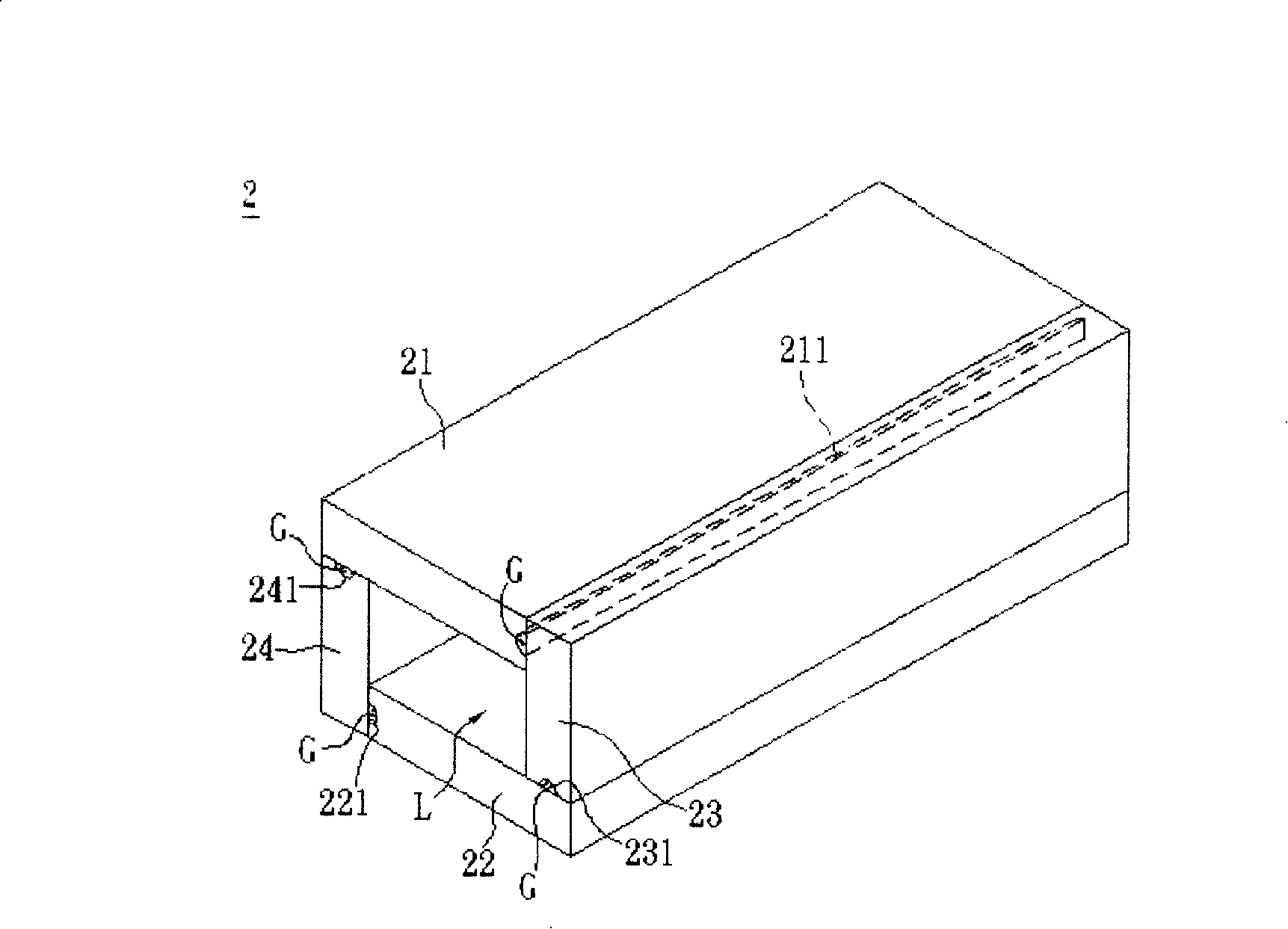
[0076] see image 3 , is the light guide 2 according to the first embodiment of the present invention, including a plurality of optical components 21, 22, 23, 24 and an adhesive G.

[0077] In this embodiment, the optical components 21 , 22 , 23 , 24 are respectively a first optical component 21 , a second optical component 22 , a third optical component 23 and a fourth optical component 24 . Wherein, these optical components 21, 22, 23, 24 are arranged in such a way that the first optical component 21 and the second optical component 22 are arranged in a misplaced position, while the third optical component 23 and the ...


PUM


Abstract

The invention discloses a light guide tube comprising a plurality of optical assemblies and an adhesive. One end of at least one optical assembly has a first concave portion. The adhesive is used to bond the optical assemblies to form a light channel and at least part of the adhesive is disposed in the first concave portion. The invention also discloses a projection system.

Description

technical field [0001] The invention relates to a display system and its light guide, in particular to a projection system and its light guide. Background technique [0002] Due to the multiple requirements of large display area, miniaturization and lightweight systems, image projection systems have become one of the most popular sub-items in the optoelectronic industry. [0003] see figure 1 As shown, the image projection system is referred to as the projection system 1 for short here, and it has a light source 10, a color wheel assembly 11, a light guide (Light Tunnel) 12, a lens assembly 13, a digital micro-mirror assembly (Digital Micro-mirror) Device, DMD) 14 and a projection unit 15. The light source 10 emits light to the color wheel assembly 11 and then enters the light guide 12, then focuses it on the digital micromirror assembly 14 through the lens assembly 13, and controls most of the micromirrors on the digital micromirror assembly 14 by driving electrodes (not ...

Claims


Application Information

Patent Timeline
Patent Type & Authority Applications(China)
IPC IPC(8): G03B21/14G03B21/00G02B6/00
Inventor 张光华赖孝武
Owner PRODISC TECH INC
Why Eureka
Try Eureka