
Exhaust structure of vacuum cleaner

A technology for vacuum cleaners and discharge pipes, applied in cleaning equipment, suction filters, vacuum cleaners, etc., can solve problems such as air leakage, increased shielding force at the suction opening, and reduced vacuum force, so as to prevent air leakage and reduce manufacturing costs Effect

Inactive Publication Date: 2008-08-13
DAEWOO ELECTRONICS CO LTD
View PDF0 Cites 1 Cited by
  • Summary
  • Abstract
  • Description
  • Claims
  • Application Information

AI Technical Summary

Problems solved by technology

[0015] If the suction opening is formed at the upper part of the dust collector and the discharge opening is formed at the lower part thereof, the vacuum force increases during the driving of the vacuum cleaner and causes the shielding force at the suction opening to increase, which causes the suction of the vacuum cleaner to be generated. Problems with reduced suction
[0016] In addition, since the discharge pipe passing through the dust collector is placed in a straight line, the pressure increase caused by the vacuum force makes the dust collector tilt to the side of the suction opening, and the connecting part around the discharge opening opposite to the suction opening is between the main body and the collection. Gaps are created between dust collectors, so vacuum force drops and air leaks occur
[0017] To solve this problem, it is necessary to provide sealing material at the suction opening and discharge opening between the dust collector and the main body, which leads to an increase in the number of parts

Method used


Image

  • Exhaust structure of vacuum cleaner
  • Exhaust structure of vacuum cleaner
  • Exhaust structure of vacuum cleaner

Examples


Embodiment Construction

[0037] Preferred embodiments of the present invention will be described in detail below with reference to the accompanying drawings.

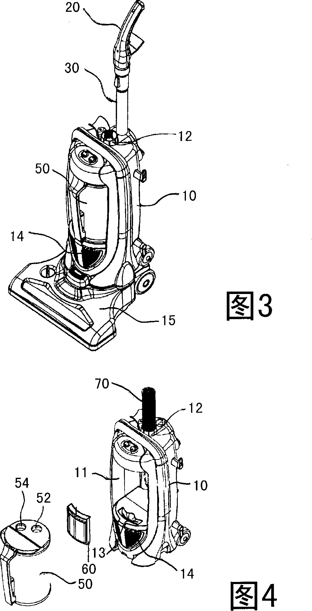
[0038] 3 is a perspective view illustrating a vacuum cleaner according to the present invention; and FIG. 4 is an exploded perspective view illustrating a dust collector of the vacuum cleaner according to the present invention.

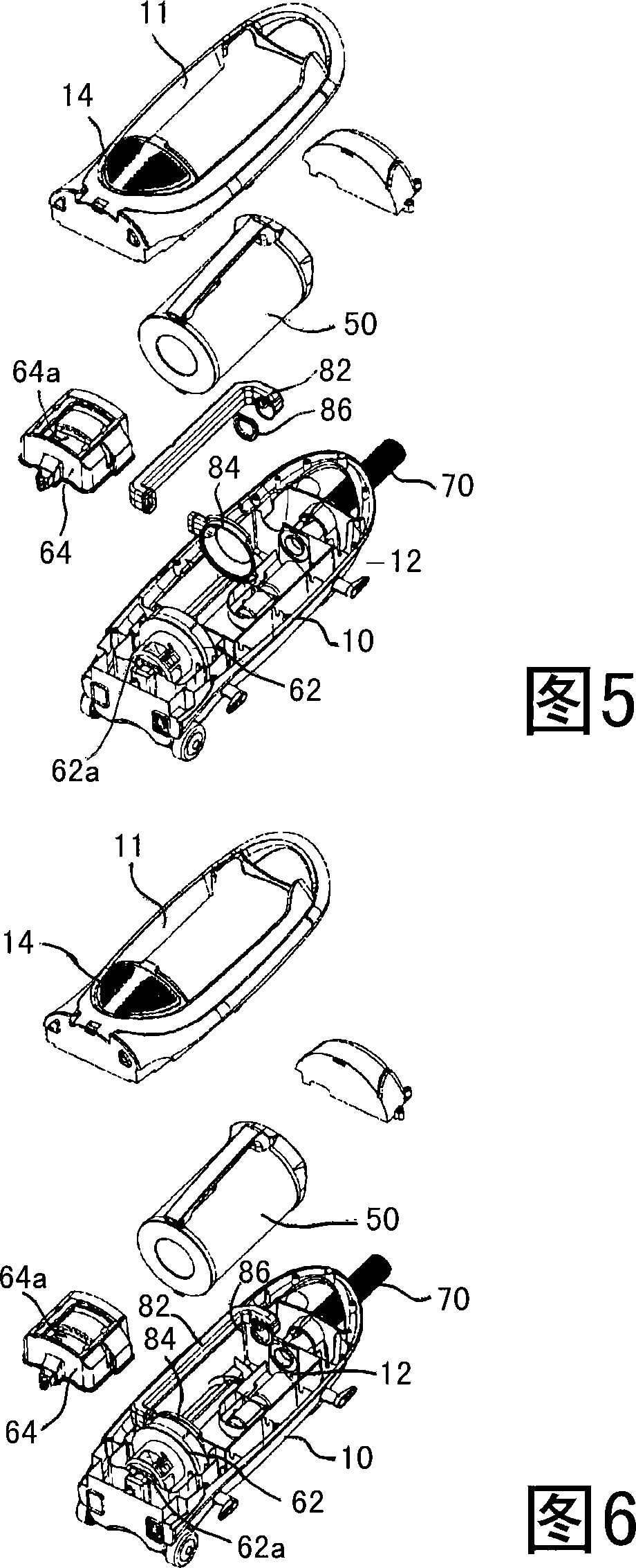
[0039] The vacuum cleaner according to the present invention includes: a main body 10 having a predetermined space therein and having a suction port 12 and a discharge port 14 thereon; a suction unit 15 detachably mounted on the lower side of the main body 10 to The main body 10 is made upright, and has a dust collection port (not shown) and a discharge opening 18; a suction hose 70, located between the suction port 12 and the discharge opening 18; an extension pipe 30, detachably installed on the main body 10 , and the interior is hollow so as to define the flow channel along which the dust is sucked; the handle 20 is...


PUM


Abstract

Disclosed herein is an exhaust structure of a vacuum cleaner. The exhaust structure of the vacuum cleaner comprises a main body 10 having a suction port 12 and a discharge port 14 formed thereon, a suction fan 62 positioned inside the discharge port 14, a dust container 50 mounted at one side of a flow passage between the suction port 12 and the discharge port 14 and having a suction opening 52 and an exhaust opening 54 formed at one side thereof, and an exhaust conduit 82 extending between the exhaust opening 54 and the discharge port 14. The exhaust structure prevents reduction in vacuum force by air leakage resulting from inclination of a dust container towards one side, and permits reduction in use of a sealing material.

Description

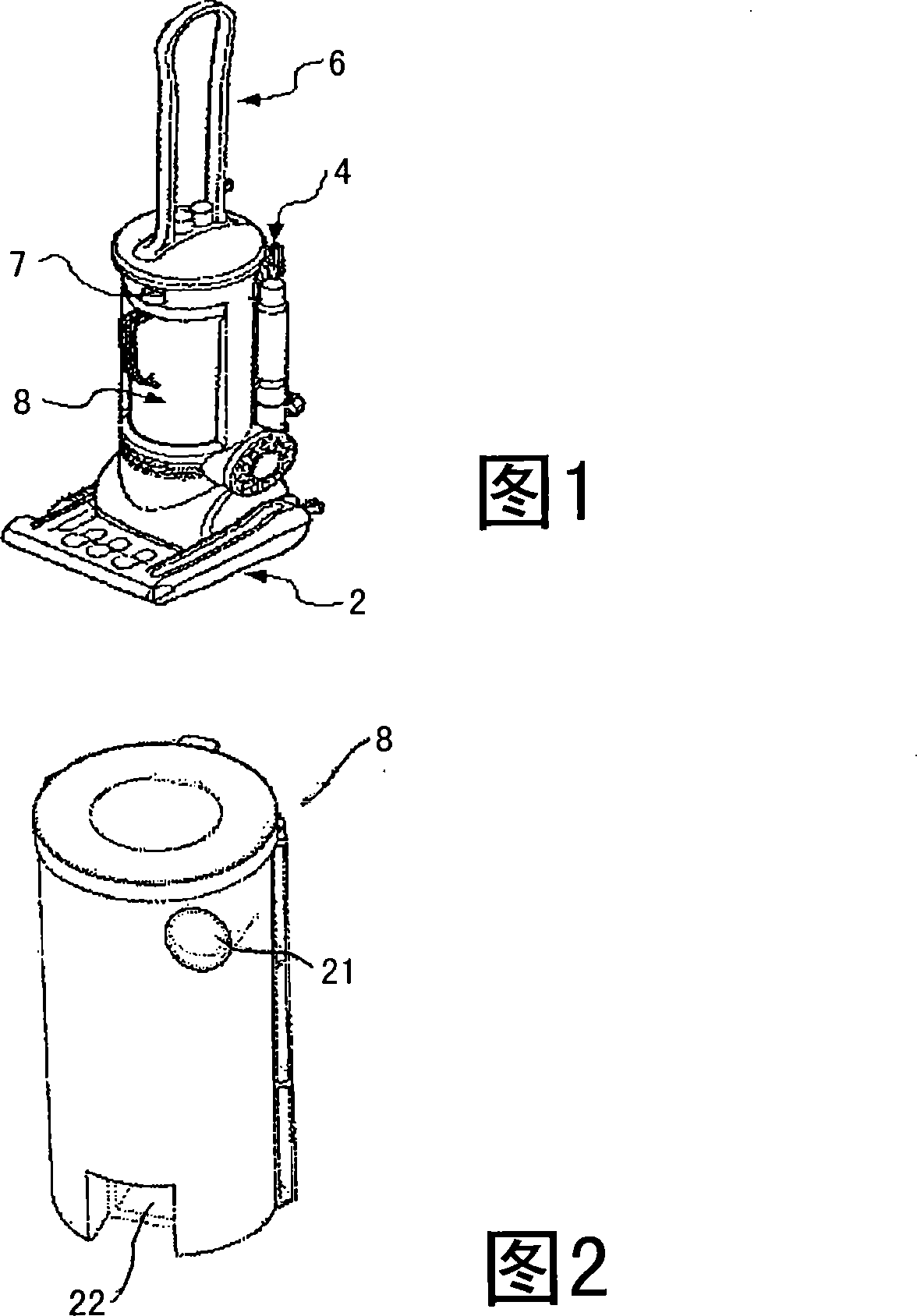
technical field [0001] The present invention relates to vacuum cleaners, and more particularly, to a discharge structure for a vacuum cleaner, which includes suction and discharge openings formed on one side of the dust collector, and a discharge pipe located outside the dust collector, thereby preventing dust collection The vacuum cleaner is tilted to one side due to pressure, so that air and impurities are drawn into the main body of the vacuum cleaner. Background technique [0002] Generally, vacuum cleaners can be classified into canister vacuum cleaners and upright vacuum cleaners according to their shape and posture during use. Canister vacuum cleaners are convenient for cleaning and moving in corners, and at the same time, it is easy to replace brushes or suction nozzles , the upright vacuum cleaner is easy to service and cleans large spaces with ease. [0003] FIG. 1 is a perspective view illustrating a conventional upright type vacuum cleaner. [0004] A conventio...

Claims


Application Information

Patent Timeline
Patent Type & Authority Applications(China)
IPC IPC(8): A47L9/00
CPCA47L9/1683A47L5/225A47L9/0081A47L5/28A47L9/00A47L9/10
Inventor 姜祥保
Owner DAEWOO ELECTRONICS CO LTD
Learn More