
High performance overhead valvetrain assembly

An overhead valve, high-performance technology, applied in the direction of valve devices, mechanical equipment, engine components, etc., can solve problems such as the rocker arm is out of position, the rocker arm is out of the expected operating position, and the installation configuration is not satisfactory.

Inactive Publication Date: 2008-08-20
GM GLOBAL TECH OPERATIONS LLC
View PDF0 Cites 4 Cited by
  • Summary
  • Abstract
  • Description
  • Claims
  • Application Information

AI Technical Summary

Problems solved by technology

This mounting configuration is often unsatisfactory as side loads on the components may cause the rocker arm to move out of its intended operating position
In addition, there is an inherent limit to the rotation of the rocker arm and the lift of the valves, which, if exceeded, will cause the rocker arm to dislodge from its position

Method used


Image

  • High performance overhead valvetrain assembly
  • High performance overhead valvetrain assembly
  • High performance overhead valvetrain assembly

Examples


Embodiment Construction

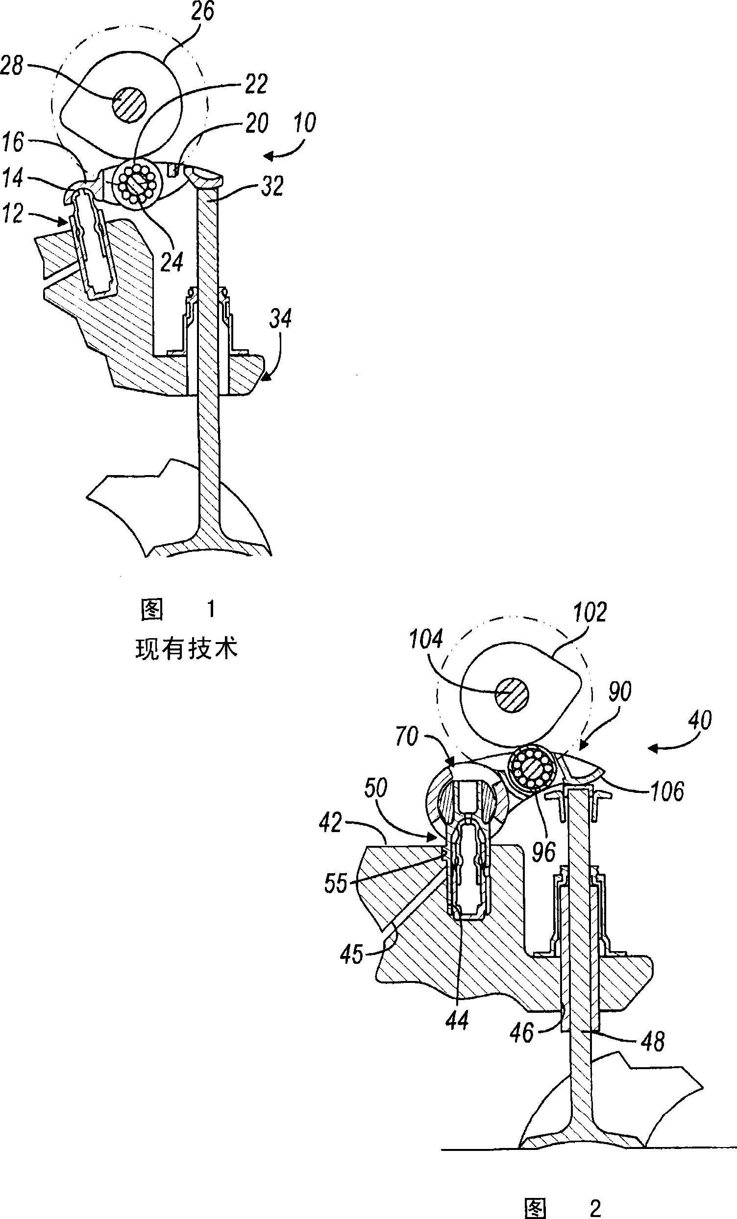
[0019] Referring now to FIG. 1 , a typical prior art valve train is shown and generally designated by the reference numeral 10 . The prior art valve train 10 includes a hydraulic lash adjuster 12 having a hemispherical end portion 14 received in a complementary hemispherical socket 16 provided at one end of a rocker arm 20 . Rocker arm 20 also includes a cam follower 22 supported by antifriction bearings such as roller or ball bearings 24 . According to a conventional embodiment, the cam follower 22 engages a cam 26 on an overhead camshaft 28 . Stem portion 32 of valve 34 is located at the end of rocker arm 20 opposite lash adjuster 12 and contacts rocker arm 20 . It should be understood that in this prior art valve configuration, the rocker arm 20 is primarily constrained within its run location. This mounting configuration limits the speed of the engine and limits valve travel or lift.

[0020] Referring now to FIG. 2 , a first embodiment of an overhead valve train 40 in...


PUM


Abstract

A high performance overhead valvetrain assembly includes a hydraulic lash adjuster which is received within and supports a trunnion. The trunnion, in turn, is received within a cylindrical passageway in one end of a rocker arm. The opposite end of the rocker arm engages a valve stem. Between the trunnion and the valve stem is a roller adapted the engage a cam of a camshaft. The trunnion stabilized rocker arm permits significantly increased valve lift and improved engine performance.

Description

[0001] Cross References to Related Applications [0002] This application claims the benefit of US Provisional Application No. 60 / 901780, filed February 16, 2007. The disclosure of the aforementioned provisional application is hereby incorporated by reference. technical field [0003] The present invention relates generally to overhead valve trains, and more particularly the present invention relates to overhead valve trains with stable rocker arms. Background technique [0004] In many conventional overhead valve configurations, one end of the rocker arm engages a lash adjuster, the opposite end engages a valve stem, and a roller or other friction reducing device in the middle of the rocker arm engages the camshaft. With this construction, there is no fixed shaft around which the rocker arm can rotate, and thus the rocker arm cannot be stabilized by being mounted on the shaft. Rather, the rocker arm must be held in its proper position by the cooperation of the male hemisp...

Claims


Application Information

Patent Timeline
Patent Type & Authority Applications(China)
IPC IPC(8): F01L1/20F01L1/22F01L1/18
CPCF01L1/185Y10T74/2107F01L2105/00F01L1/2405F01L2305/00
Inventor A·W·海曼R·S·麦卡尔平E·C·杜斯
Owner GM GLOBAL TECH OPERATIONS LLC
Learn More