Quick positioning locking mechanism

A positioning locking and fast technology, applied in the direction of bolts, etc., to achieve the effect of quick disassembly and easy disassembly

Inactive Publication Date: 2008-08-27
CHANGCHUN INST OF OPTICS FINE MECHANICS & PHYSICS CHINESE ACAD OF SCI
View PDF0 Cites 22 Cited by
  • Summary
  • Abstract
  • Description
  • Claims
  • Application Information

AI Technical Summary

Problems solved by technology

[0003] The purpose of the present invention is to propose a fast positioning and locking mechanism that is easy to disassemble and safe and reliable, so as to overcome the shortcomings of the current traditional positioning and locking mechanism

Method used


Image

  • Quick positioning locking mechanism
  • Quick positioning locking mechanism
  • Quick positioning locking mechanism

Examples


Embodiment 1

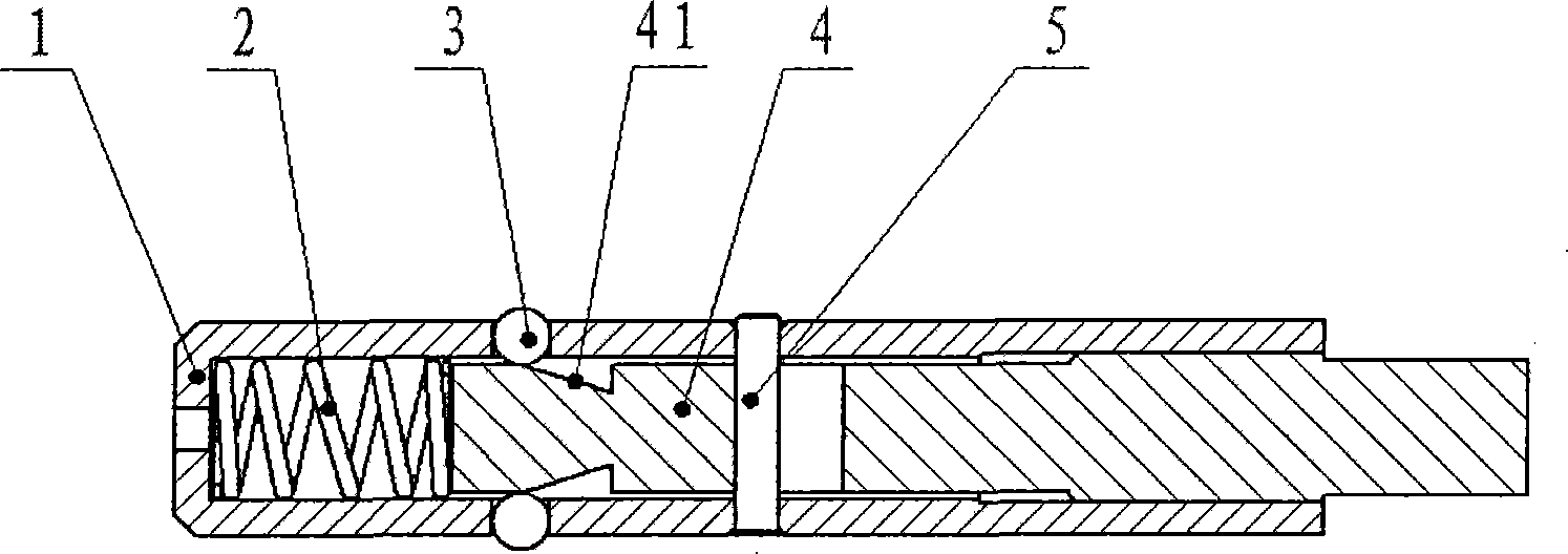
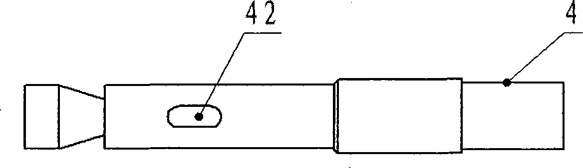
[0014] refer to figure 1 , 2 , a fast positioning locking mechanism, including a lock sleeve 1 with a bottom cover at one end, a pin shaft 4 that can slide axially in the inner cavity of the lock sleeve 1, and is arranged at the bottom end of the inner cavity of the lock sleeve 1 and the left end of the pin shaft 4 The compression spring 2 that part conflicts; On the right side of the end portion where the pin shaft 4 abuts against the compression spring 2, a section of conical surface 41 constricting to the right is provided, and on the pin shaft 4 on the right side of the conical surface 41, there is a hole that runs through it. The diameter of the axial guide groove 42, a limit guide post 5 that can slide axially along the pin shaft 4 is inserted in the axial guide slot 42, and the two ends of the guide post 5 are inserted in the lock sleeve 1 On the cavity wall; on the cavity wall of the lock sleeve 1, there are two radially symmetrical through holes corresponding to the ...


PUM


Abstract

The invention relates to a locating locking mechanism used between two parts with relative motion inside a mechanical drive device, in particular to a quick locating locking mechanism capable of realizing quick disassembly. The mechanism comprises a lock casing with one end provided with a bottom closing, a pin shaft arranged inside the intracavity of the lock casing and capable of sliding in axial direction and a pressure spring arranged at the bottom end of the intracavity of the lock casing, wherein the right side of the end part of the pin shaft pressed on the pressure spring is provided with a conical surface necking down to the right; a pin shaft which is arranged on the right of the conical surface is provided with an axial guiding groove running through the diameter of the pin shaft; a stop guiding column capable of sliding along the axial direction of the pin shaft is inserted into the axial guiding groove; both ends of the guiding column are inserted into the cavity wall of the lock casing; the cavity wall of the lock casing corresponding to the conical bottom of the conical surface of the pin shaft is provided with two through holes of radial symmetry; moreover, pin bodies which can freely slide inside the two through holes are respectively placed inside both through holes. The quick locating locking mechanism, which is convenient for quick disassembly, is safe and reliable and does not fall off automatically during operation.

Description

technical field [0001] The invention relates to a positioning and locking mechanism for two parts with relative movement in a mechanical transmission device, in particular to a quickly detachable positioning and locking mechanism. Background technique [0002] Between two relative moving parts in the mechanical transmission device, sometimes it is necessary to make it intermittent non-relative movement. The traditional method is to insert a direct pin between the two parts to realize positioning or to use other mechanisms to realize fixation. Although the direct pin can ensure the positioning of the mechanism in the direction of motion, it is prone to axial movement and fall off under the action of external force, which cannot guarantee the safe and reliable operation of the mechanism; although it is safe to fix with other mechanisms, it takes a long time to disassemble and install , high cost and large space occupation. Contents of the invention [0003] The object of th...

Claims


Application Information

Patent Timeline
Patent Type & Authority Applications(China)
IPC IPC(8): F16B19/02
Inventor 陈伟惠守文张景国
Owner CHANGCHUN INST OF OPTICS FINE MECHANICS & PHYSICS CHINESE ACAD OF SCI
Why Eureka
Try Eureka