Optical image measurement device

A light image and measurement technology, which is applied in the direction of measuring devices, optical devices, eye testing equipment, etc., can solve problems such as the inability of the eye to be fixed

Inactive Publication Date: 2008-08-27
KK TOPCON
View PDF6 Cites 15 Cited by
  • Summary
  • Abstract
  • Description
  • Claims
  • Application Information

AI Technical Summary

Problems solved by technology

Therefore, there will also be such a problem that when the signal light is used to scan the fundus, the subject's eyes will follow the scanning trajectory, making the subject's eyes unable to fix their vision.

Method used


Image

  • Optical image measurement device
  • Optical image measurement device
  • Optical image measurement device

Examples


Embodiment Construction

[0092] An example of a preferred embodiment of the optical image measuring device and the program for controlling the optical image measuring device of the present invention will be described in detail with reference to the drawings.

[0093] Two embodiments of the present invention will be described below. In the first embodiment, a three-dimensional image is formed based on a plurality of tomographic images of an object to be measured. In addition, the second embodiment generates predetermined characteristic information based on a plurality of tomographic images of the object to be measured.

[0094]

[0095] [device structure]

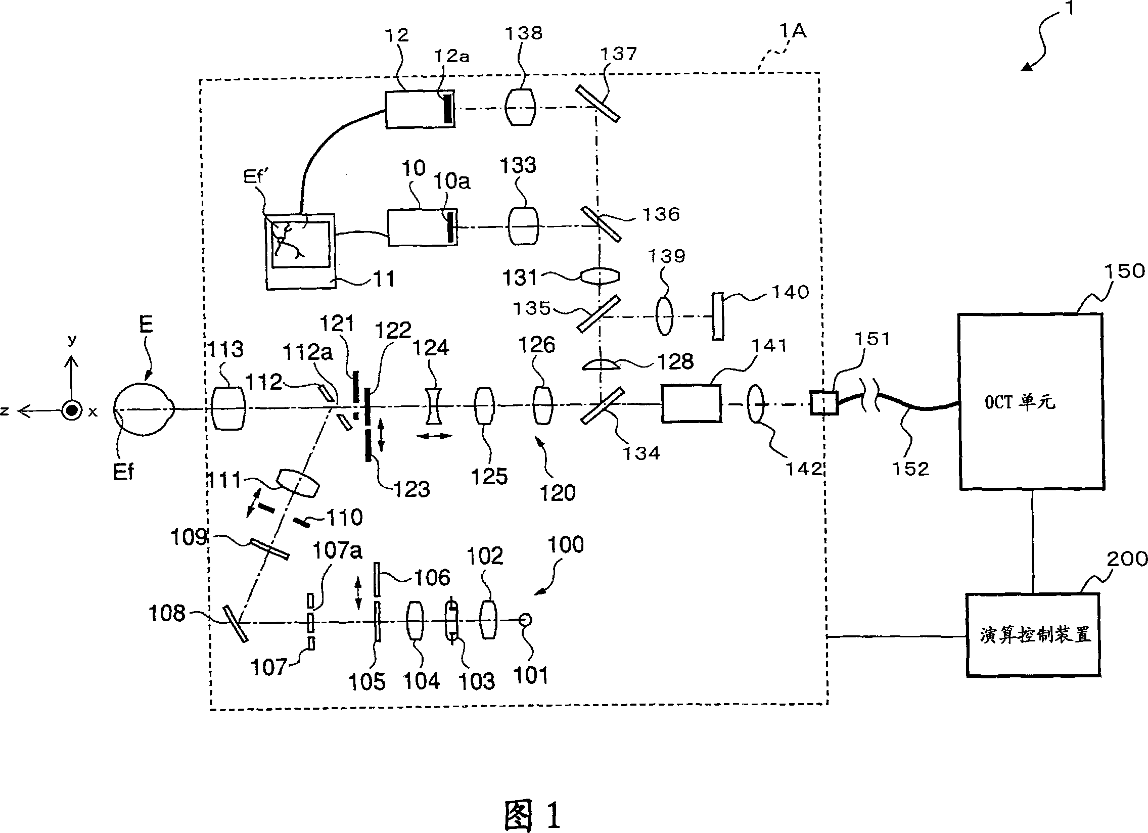
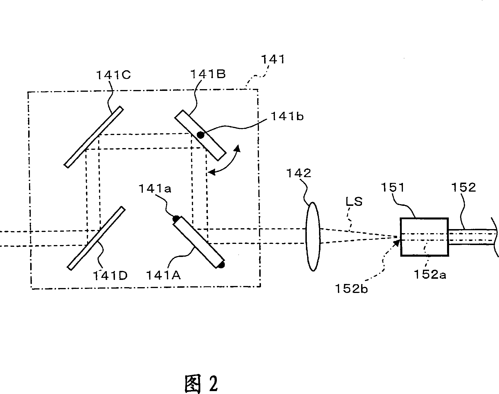
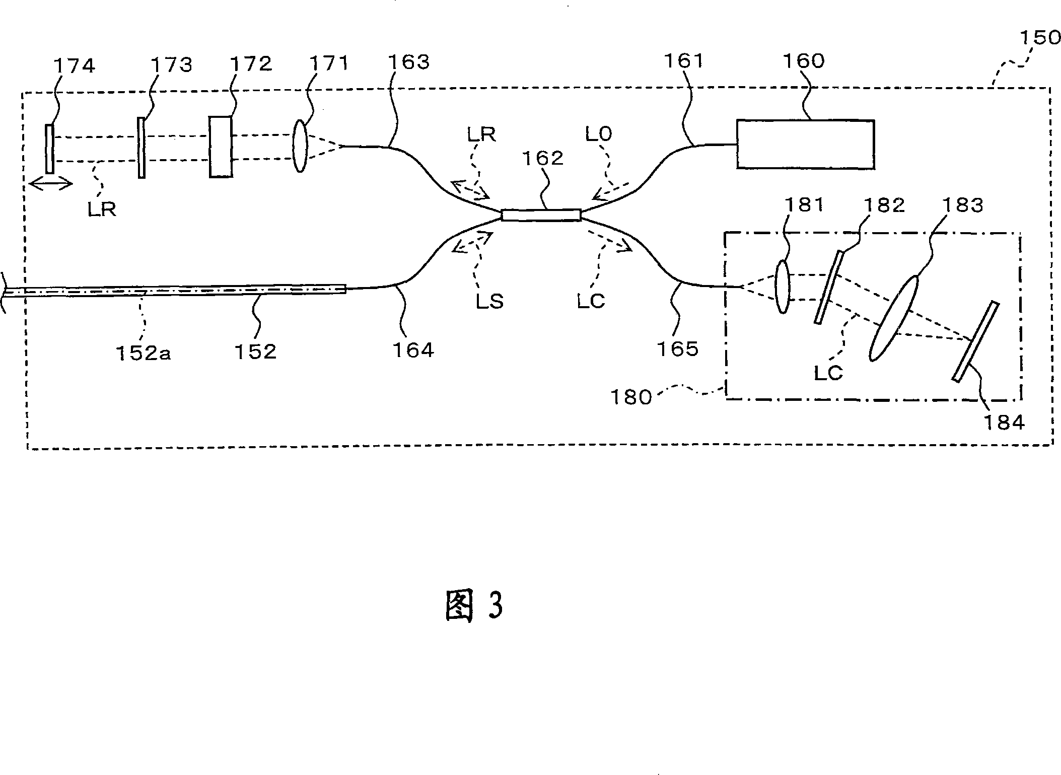
[0096] First, the configuration of a first embodiment of the optical image measuring device of the present invention will be described with reference to FIGS. 1 to 6 . Here, FIG. 1 shows an example of the overall configuration of a fundus observation device 1 having the function of an optical image measurement device of the present invention. F...


PUM


Abstract

Fixation vision of the examined eye is provided effectively when an image of the examined eye is to be acquired. Low coherent light (L0) is divided into signal light (Ls) facing eyeground (Ef) and referential light (LR) facing a referential lens (174) by an eyeground observing device (a light image measuring device). Interference light (LC) is generated by overlapping the signal light (LS) passing the eyeground (Ef) and the referential light (LR) passing the referential lens (174). A tomographic image is formed by detecting the reference light (LC). A radial tomographic image (Gi) with a plurality of sections are obtained by scanning signal light along a plurality of radial scanning lines (Ri). A 3D image forming section (231) forms 3D images with scanning line (Ri) intervals under a threshold value. In addition, numbers and scanning lines corresponding to the assigned region are set automatically when an eyeground region is assigned. In addition, a 3D image with a region corresponding with the assigned numbers when numbers of the scanning lines are assigned.

Description

technical field [0001] The present invention relates to an optical image measuring device, which irradiates a light beam onto an object to be measured, and uses the reflected light or transmitted light to form an image of the surface form or internal form of the object to be measured. Background technique [0002] In recent years, optical image measurement technology that forms an image showing the surface shape or internal shape of an object to be measured using a beam of light such as a laser light source has attracted attention. This optical image measurement technology is expected to be applied in the medical field because it is not invasive to the human body like X-ray CT equipment. [0003] Japanese Patent Application Laid-Open Publication No. 11-325849 (Patent Document 1) discloses an optical image measuring device, the structure of which is: the measuring arm scans the object through a rotating steering mirror (galvanometer mirror). A reference mirror is set on the ...

Claims


Application Information

Patent Timeline
Patent Type & Authority Applications(China)
IPC IPC(8): G01B9/02
CPCG01B2290/65A61B3/102G01B9/02044G01B9/02091G01N21/4795G01B9/0203G01N2021/1787G01B9/02089
Inventor 木川勉诹访明宏
Owner KK TOPCON
Why Eureka
Try Eureka