Threshing apparatus

A technology of threshing and sorting device, which is applied in threshing equipment, applications, agricultural machinery and implements, etc., can solve the problems of unpredictable sorting performance and no screening function, and achieve accurate and good separation and sorting, The effect of improved sorting performance

Active Publication Date: 2008-09-03
ISEKI & CO LTD
View PDF2 Cites 6 Cited by
  • Summary
  • Abstract
  • Description
  • Claims
  • Application Information

AI Technical Summary

Benefits of technology

This patented technology describes an apparatus called a separator or scavenger where two different paths are provided: one goes straight towards another while other ones go diagonally across them. These branches help sort out larger particles and shredded waste during processing. By adjusting these steps based upon factors like size and shape of each particle, this system allows accurate and efficient sorting of both types of product. Additionally, there may include multiple stages of cleanings between the main process sections before and after it falls onto the final stage of the machine. Overall, this design enhances the quality control capabilities and efficiency of the overall production line's equipment.

Problems solved by technology

Prior Art describes different ways to improve the efficiency of separating materials during processing such as mills or sieves used for creation of products like paper pulp. However, these techniques may result in some particles getting stuck between them due to gravity when they fall onto other parts of the machine. These particles can cause damage if left unattended over time. Therefore, an improved separation technique needs to be developed without causing any harm caused by this issue.

Method used


Image

  • Threshing apparatus
  • Threshing apparatus
  • Threshing apparatus

Examples


Embodiment Construction

[0032] Hereinafter, the embodiment of this invention is concretely demonstrated based on drawing.

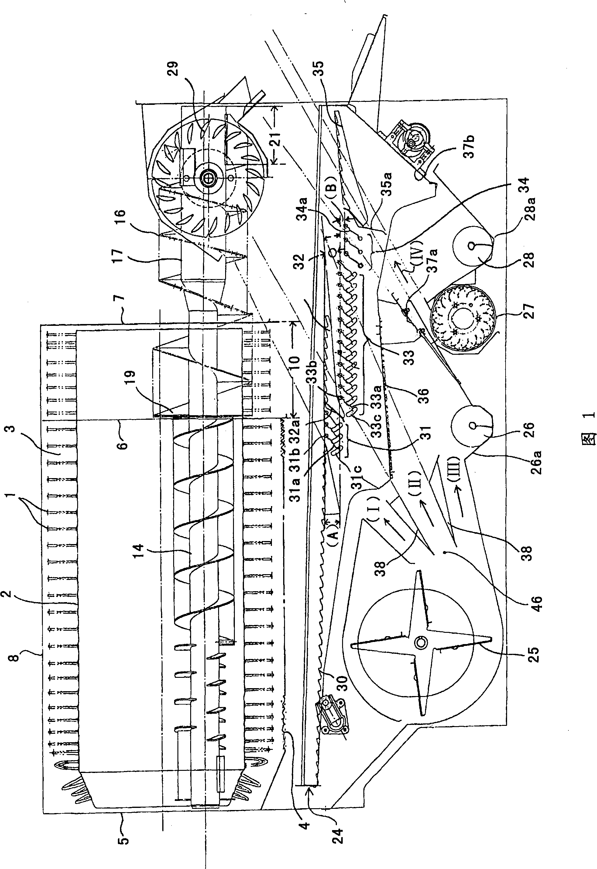
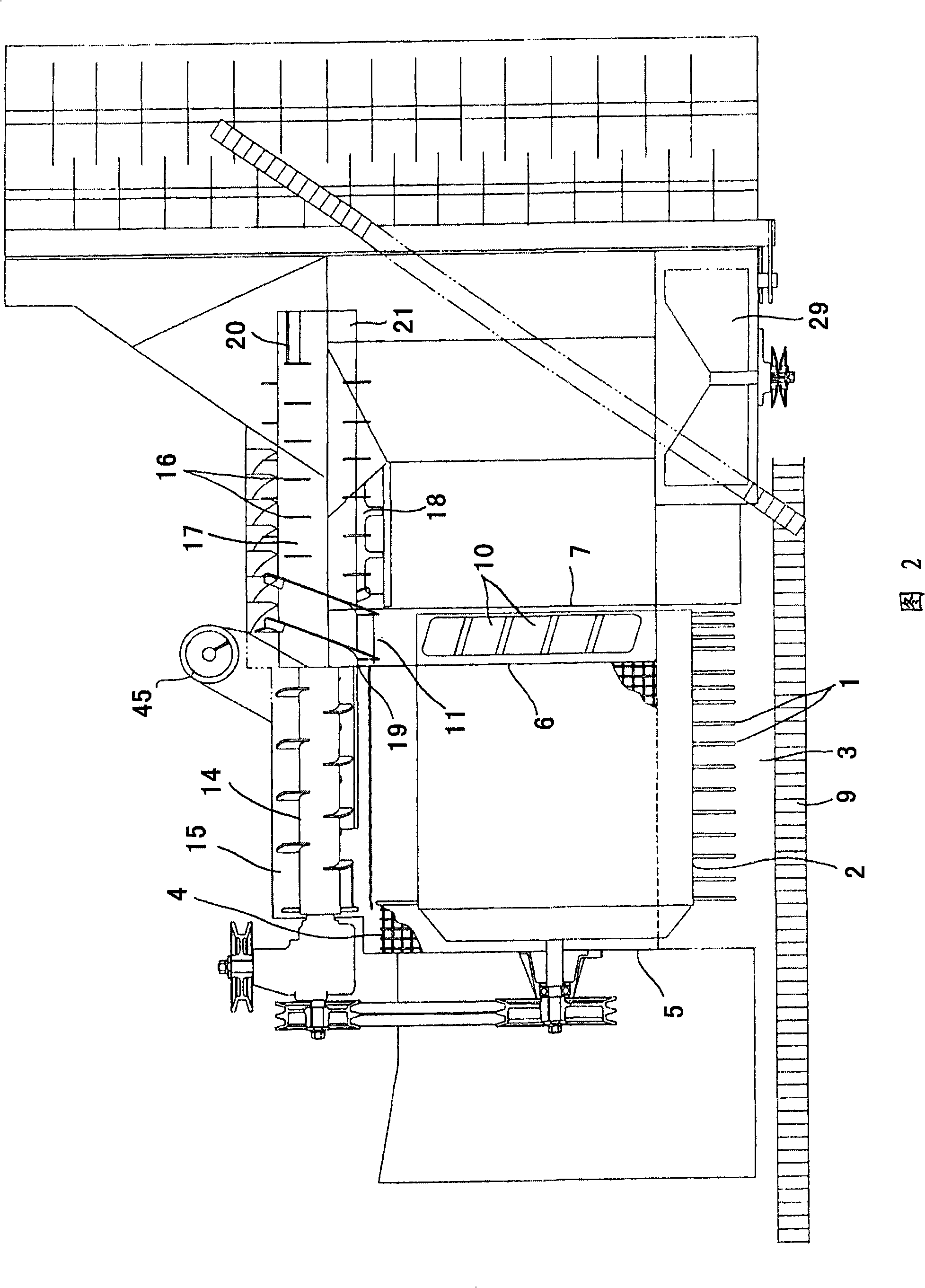
[0033] Fig. 1 and Fig. 2 show a threshing device mounted on a combine harvester.

[0034] The receiving net 4 is spread and arranged along the lower half circumference of the threshing chamber 3 in which the threshing drum 2 with the threshing gear 1 is rotatably installed. The receiving net 4 is arranged between the front side plate 5 and the middle side plate 6 of the threshing chamber. 8 is the threshing cylinder cover that covers the upper part of the threshing chamber 3, and is made into a structure that can swing open and close around the axis parallel to the rotation axis of the threshing cylinder 2.

[0035] On the side of the threshing port of the threshing chamber 3, a threshing feed chain 9 for clamping and transporting straw is provided. The terminal side of the threshing chamber 3 is provided with a first dust discharge port 10 that makes the dust discharge treatm...


PUM


Abstract

The invention relates to a threshing device, which improves the separation performance by setting a regulated fall in the separation path of a glume sieve. The front end part of the glume sieve (33) is disposed a position lower than the back end part of a first glume sieve (31), forming a first step (A). In addition, the front end part of a third glume sieve (34) is arranged in a position lower than the back end part of the second glume sieve (34), forming a second step (B). Besides, a blowing path for blowing towards the first step (A) and the second step (B) is formed.

Description


Claims


Application Information

Patent Timeline
Owner ISEKI & CO LTD
Why Eureka
Try Eureka