
Method for operating inking device of printer

A technology of printing ink and ink infusion, which is applied to the general parts of printing machinery, printing machines, printing, etc., and can solve problems such as the difficulty of accurately measuring the amount of ink

Inactive Publication Date: 2008-09-03
M A N ROLAND DRUCKMASCHINEN AG
View PDF0 Cites 4 Cited by
  • Summary
  • Abstract
  • Description
  • Claims
  • Application Information

AI Technical Summary

Problems solved by technology

It is therefore very difficult to precisely meter the amount of ink on inking units with inking rollers under operating conditions in which the thickness of the ink layer on the inking roller roughly corresponds to the gap width between the inking roller and the inking roller
[0004] After the inking roller, it is placed on the inking unit of a lifting roller. In this connection, precise metering is possible, but the oscillating movement of the lifting roller causes vibrations in the printing machine. This vibration is especially unacceptable on high-speed rotary printing presses.

Method used


Image

  • Method for operating inking device of printer
  • Method for operating inking device of printer
  • Method for operating inking device of printer

Examples


Embodiment Construction

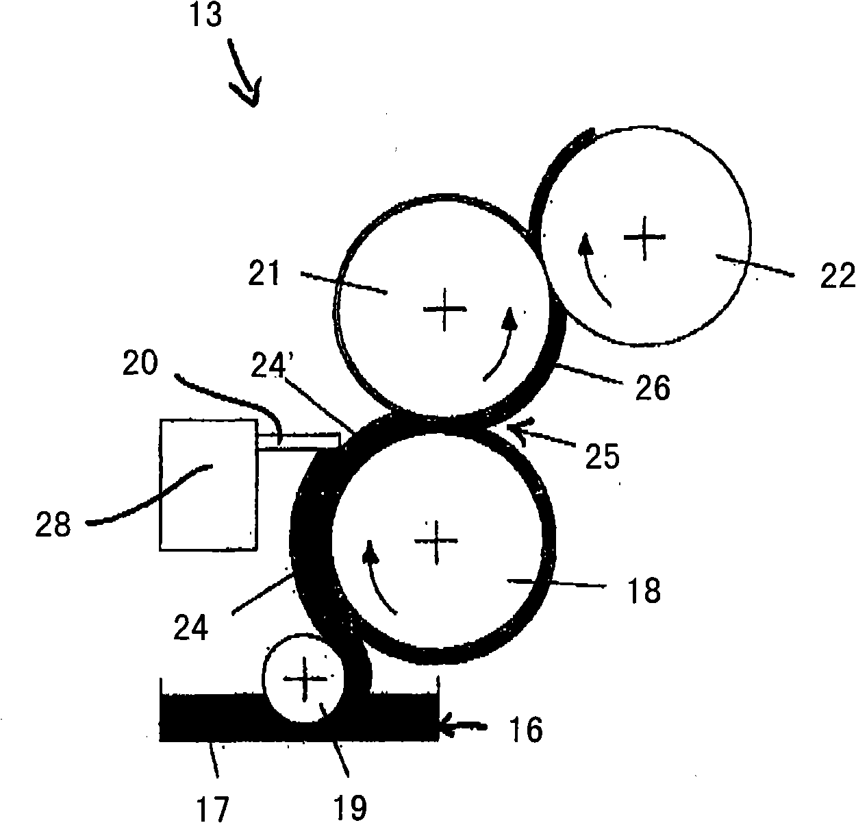
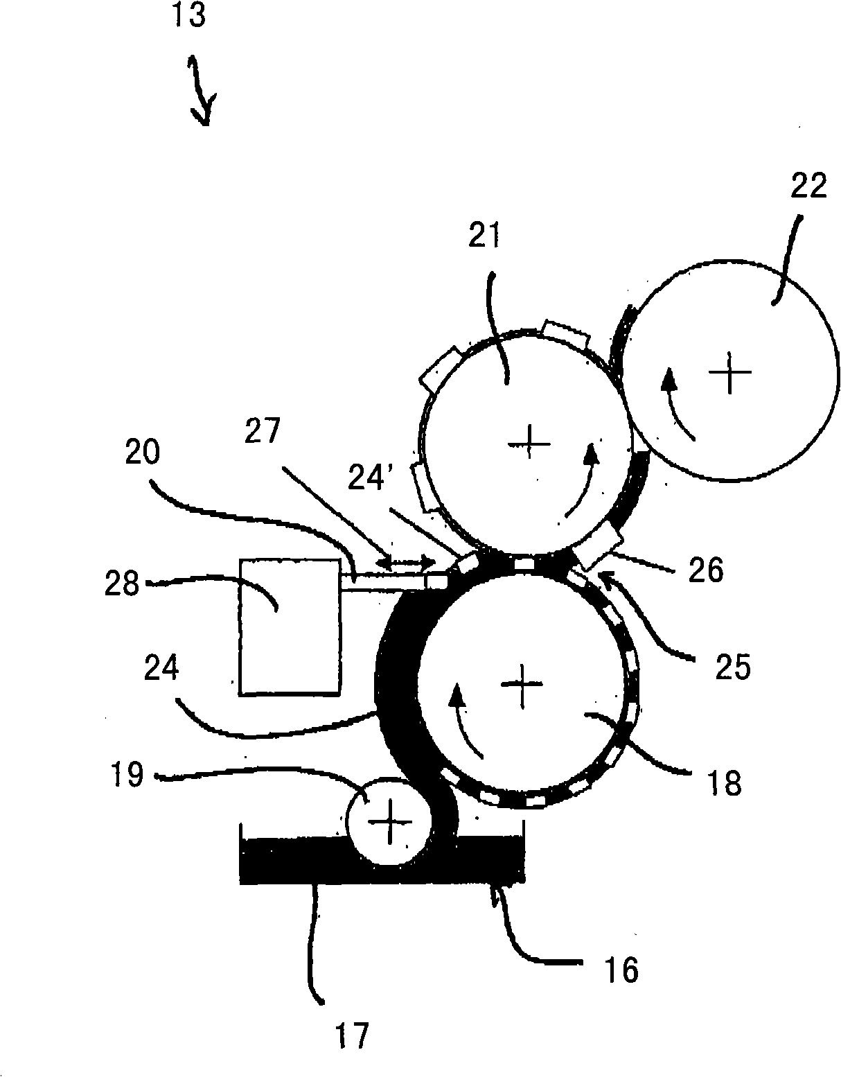
[0032] With the help of Figures 1 to 3 The present invention will be described in detail.

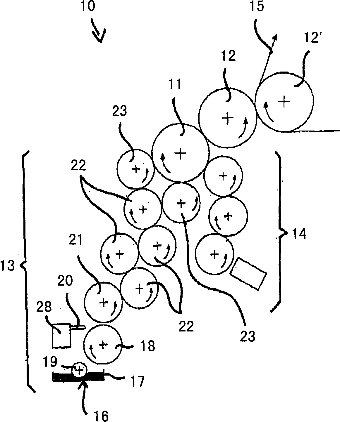
[0033] figure 1 A schematic diagram of a printing unit 10 of a rotary printing press is shown, wherein the printing unit 10 includes a printing plate cylinder 11 , a transfer cylinder 12 , an inking unit 13 and a dampening unit 14 . The printing ink is applied to at least one printing plate positioned on the plate cylinder 11 by means of the inking unit 13 , while the dampening agent can be applied to the or each printing plate by means of the dampening unit 14 . The printing ink coated on the plate cylinder 11 is transferred to the printing material 15 by means of the transfer cylinder 12, wherein, according to figure 1 On the transfer cylinder 12 of the printing unit 10 the transfer cylinder 12 ′ of the other printing unit is rolled.

[0034] The inking unit 13 of the printing unit 10 has an ink fountain 16 in which printing ink 17 is prepared. The inking roller 18 draws printing...


PUM


Abstract

The method involves receiving a printing ink provided in a color box (16) of an inking system in a ductor-roller (18). A color zone from the color box to the ductor roller is adjusted to a color quantity to be transferred. The printing ink is transferred from the ductor roller to an inking system roller that is downstream to a film roller. A color slider or ink-ductor blade (20) is controlled such that zonal changes the color quantity at a circumference of the ductor roller, where the color quantity is transferred to the ductor roller.

Description

technical field [0001] The invention relates to a method for operating an inking unit of a printing press according to the preamble of claim 1 . Background technique [0002] The inking unit of the printing press has an ink fountain with printing ink therein, wherein the ink provided in the ink fountain is drawn from the ink fountain by an ink feed roller. The amount of ink required on the printed material can vary from area to area or vary from area to area, so that the amount of ink transferred from the ink fountain to the inking roller can be adjusted for each ink area by means of a so-called doctor blade or doctor blade . An inking roller or a lift roller is arranged downstream of the inking roller, which removes the printing ink from the inking roller and transfers it to at least one inking unit roller downstream of the inking roller or lifting roller. The printing ink passes through individual or per inking unit rollers which are placed behind ink film rollers or lif...

Claims


Application Information

Patent Timeline
Patent Type & Authority Applications(China)
IPC IPC(8): B41F31/04B41F31/12
CPCB41F31/04B41F31/045B41F31/06
Inventor N·迪拉R·赫特T·约翰R·纳格勒
Owner M A N ROLAND DRUCKMASCHINEN AG
Learn More