Blanket cylinder with integrated compressible layer

a compression layer and blanket technology, applied in the field of printing presses, can solve the problems of reducing the pliancy of the multi-layer blanket, the difficulty of manufacturing and expensive, and the loss of pliancy (i.e. stiffness) of the blanket, and the gage (i.e. diameter) of the current multi-layer blank

Inactive Publication Date: 2005-03-08
SHANGHAI ELECTRICGROUP CORP
View PDF17 Cites 64 Cited by
  • Summary
  • Abstract
  • Description
  • Claims
  • Application Information

AI Technical Summary

Problems solved by technology

Sleeve-shaped blankets having this construction can be especially bulky to ship and store.
Their multi-layer construction makes them difficult to manufacture and expensive.
Also, current multi-layer blankets lose pliancy (i.e. stiffness) and gage (i.e. diameter) over time due to degradation of the matrix material, especially the compressible material.

Method used


Image

  • Blanket cylinder with integrated compressible layer
  • Blanket cylinder with integrated compressible layer
  • Blanket cylinder with integrated compressible layer

Examples


Embodiment Construction

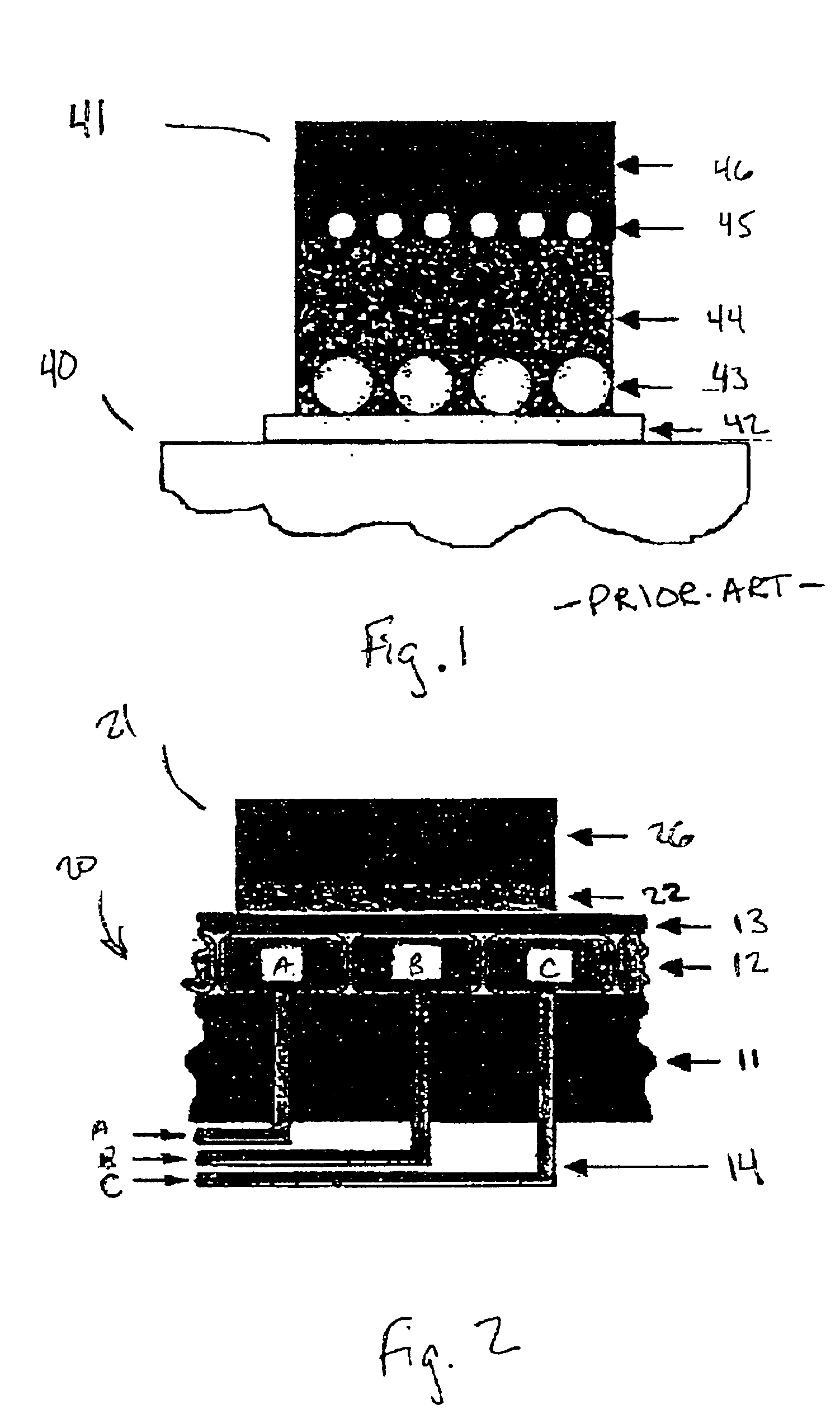
FIG. 1 shows a schematic partial cross-section of a prior art blanket cylinder 40 having a prior art printing blanket 41 disposed thereon. Prior art printing blanket includes multiple layers. Sleeve 42 is disposed directly adjacent to blanket cylinder 40 and is permanently bonded to the rubber layers surrounding it. Base cord 43 is disposed adjacent to sleeve 42 and may include cotton or polymer thread aligned around the circumference of blanket cylinder 40. Compressible layer 44 may be made of nitrile foam rubber and is bonded to and surrounds base cord 43. Reinforcing cord may include cotton or polymer threads aligned circumferentially around an outer region of the compressible layer. Print layer 46 is bonded to the outside of reinforcing cord 45. Base cord and reinforcing cord provide stability and strength to the multi-layer blanket structure resulting in a more stable print surface.

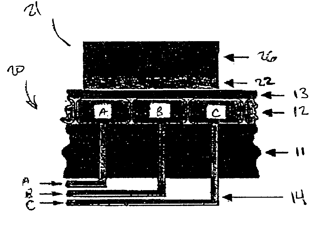
High speed printing causes the compressible layer to repeatedly contract and expand as the print ...


PUM


Abstract

A printing unit including a rigid cylinder rotatable about an axis of rotation, a plurality of inflatable bladders disposed on a circumferential surface of the cylinder, and a first fluid supply regulation unit configured to supply a first fluid to a first set of inflatable bladders of the plurality of inflatable bladders and to regulate a first fluid pressure inside the first set inflatable bladders. In addition, a method for mounting a sleeve-shaped printing sock onto a blanket cylinder of an offset printing press, in which a set of inflatable bladders disposed at an outer region of the blanket cylinder are at least partially deflated. The sleeve-shaped printing sock is slid over one end of the blanket cylinder so that the printing sock at least partially surrounds a circumference of the blanket cylinder. The set of inflatable bladders are then inflated so that the printing sock fits tightly around the circumference of the blanket cylinder.

Description

BACKGROUND OF THE INVENTIONThe present invention relates generally to printing presses and more particularly to a blanket cylinder including an integrated compressible layer.Offset lithographic printing presses, for example, have a plate cylinder and a blanket cylinder for transferring images from a printing cylinder to a web of material, such as paper.The circumferential surface of the blanket cylinder is typically covered with a multi-layer compressible blanket having an outer print layer which receives the images from the printing plate and transfers them onto the web of material. The blanket may be a flat material wrapped around and secured to the blanket cylinder, or, in the case of gapless printing presses, it may be a sleeve-shaped material for slipping over one end of the blanket cylinder.Printing blankets in the prior art include a print layer, a layer of reinforcing cord, a compressible layer, a base cord, and a sleeve which contacts a metal circumferential surface of the ...

Claims


Application Information

Patent Timeline
Patent Type & Authority Patents(United States)
IPC IPC(8): B41F27/00B41F27/10B41F30/00B41F30/04B41F13/18B41N10/00
CPCB41F27/105B41F30/04B41P2227/20
Inventor BELANGER, JAMES RICHARDWEILER, RICHARD KARL
Owner SHANGHAI ELECTRICGROUP CORP
Why Eureka
Try Eureka