Oil-submersible electric membrane pump

A diaphragm pump and electric technology, applied in pumps, machines/engines, pumps with flexible working elements, etc., can solve problems such as increased energy consumption, reduced oil discharge, and reduced pump efficiency

Active Publication Date: 2010-06-02
山东创佳新能源科技有限公司
View PDF5 Cites 0 Cited by
  • Summary
  • Abstract
  • Description
  • Claims
  • Application Information

AI Technical Summary

Problems solved by technology

With the prolongation of the underground oil extraction period, a large number of low-permeability oil wells have appeared, and the oil discharge (permeation) volume has decreased. The continued use of the existing submersible electric pump will inevitably lead to the operation of the submersible electric pump under low load. Reduced and relatively increased energy consumption

Method used


Image

  • Oil-submersible electric membrane pump
  • Oil-submersible electric membrane pump

Examples


Embodiment 1

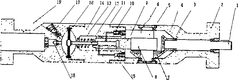
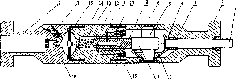
[0008] Embodiment 1: Referring to the accompanying drawings, the pump body is composed of three parts, the upper pump body 19, the middle pump body 14 and the lower pump body 2, which are connected by threads to form a whole. The lower part of the lower pump body 2 is axially penetrated with a transmission shaft 1, the exposed part of the transmission shaft 1 is connected with the motor, the upper part of the transmission shaft 1 is connected with an axial bevel gear 4, and the joint between the transmission shaft 1 and the lower pump body 2 is provided There are sealed bearings3. A camshaft 5 is radially fixed in the upper chamber of the lower pump body 2, and a cam 8 is arranged in the middle of the camshaft 5. Bearings and bearing caps 6 are arranged at both ends of the camshaft 5 and the junction of the lower pump body 2. On the camshaft 5 A radial bevel gear 7 engaged with the axial bevel gear 4 is fixed to realize the radial rotation of the camshaft 5 . The cavity is fi...

Embodiment 2

[0011] Embodiment 2: On the basis of the above embodiments, the plunger bushing 11 is omitted, which has the same effect, but the smooth and sealing fit between the plunger 9 and the inner wall of the intermediate pump body 14 must be maintained. The lower pump body 2 and the upper pump body 19 have a flange at the end, which is convenient for the lower end of the pump to be connected to the motor, and the upper part to be connected to the pipe string. The pump body is connected by threads, and the seal is reliable. For smaller wellbores.

[0012] Its working principle is: the transmission shaft is connected with the submersible motor, and the motor drives the bevel gear on the transmission shaft to rotate, and transmits the power to the radial bevel gear, which rotates together with the camshaft and the cam, pushing the plunger to reciprocate up and down, through The oil drain valve and the oil inlet valve suck and discharge the hydraulic oil in the lower pump body, and push ...


PUM


Abstract

The present invention relates to a submersible electric diaphragm pump related to field of submersible electric pump. The pump is consisted of an upper pump body, a middle pump body and a lower pump body, the lower pump body has a transmission shaft, an axial bevel gear, a radial bevel gear, a camshaft and a cam; the middle pump body has a piston, a bush, a slide valve, an oil drain valve, an induction valve and a spring in it; a septum is provide between the upper pump body and the middle pump body to separate lubricant and well liquid, a suction valve and a vent valve are mounted in the upper pump body. The present invention improved totally the impeller (turbine) direct aspiration of present submersible electric pump in structure, realizes septum working cavity shrinking and expending by to-and-fro motion driven by piston to realize pump drain of oil finally, reaches the target of small displacement mining oil in high efficiency and energy efficiency.

Description

technical field [0001] The invention relates to a submersible electric diaphragm pump in the field of electric submersible pumps. Background technique [0002] The combination of submersible electric pump and motor to achieve downhole oil recovery is a commonly used technical means in the field of oil extraction. The currently used submersible electric pump mainly pumps the oil outside the pump body into the oil pipe through the rotating impeller in the pump body to realize the collection of downhole oil. This kind of pump has the characteristics of large displacement to collect underground oil. With the prolongation of the underground oil extraction period, a large number of low-permeability oil wells have appeared, and the oil discharge (permeation) volume has decreased. The continued use of the existing submersible electric pump will inevitably lead to the operation of the submersible electric pump under low load. The problem of reducing and relatively increasing energy ...

Claims


Application Information

Patent Timeline
Patent Type & Authority Patents(China)
IPC IPC(8): F04B43/04
Inventor 孙殿甲谢伟郑家远
Owner 山东创佳新能源科技有限公司
Why Eureka
Try Eureka