Unpowered automatic vacuum siphon auxiliary device

An auxiliary device and evacuation device technology, applied in non-electric variable control, instrument, control/regulation system, etc., can solve the problems of unstable operation of siphon device, inability to achieve siphon phenomenon, harsh other conditions, etc., and achieve simple structure and operation. Convenient, force-reducing effect

Active Publication Date: 2018-02-27
上海碧兰环保技术开发有限公司
View PDF8 Cites 0 Cited by
  • Summary
  • Abstract
  • Description
  • Claims
  • Application Information

AI Technical Summary

Problems solved by technology

[0004] The advantages of using auxiliary siphon to generate siphon are: it has the function of energy saving and automatic water level control; the disadvantage is that its design and other conditions for forming siphon are relatively harsh, and it often happens that the siphon cannot be achieved, resulting in unstable operation of the siphon device, such as in the siphon filter. Such problems often occur in use;
[0005] The use of vacuum pump to assist vacuum to generate siphon has the advantages of stable operation and precise control, but the disadvantage is that it needs power and consumes energy; in addition, it needs to increase electrical equipment such as vacuum suction equipment and automatic control, which makes the initial investment higher.

Method used


Image

  • Unpowered automatic vacuum siphon auxiliary device
  • Unpowered automatic vacuum siphon auxiliary device
  • Unpowered automatic vacuum siphon auxiliary device

Examples


Embodiment Construction

[0061] In order to more clearly illustrate the embodiments of the present invention or the technical solutions in the prior art, the specific implementation manners of the present invention will be described below with reference to the accompanying drawings. Obviously, the accompanying drawings in the following description are only some embodiments of the present invention, and those skilled in the art can obtain other accompanying drawings based on these drawings and obtain other implementations.

[0062] In order to make the drawing concise, each drawing only schematically shows the parts related to the present invention, and they do not represent the actual structure of the product. In addition, to make the drawings concise and easy to understand, in some drawings, only one of the components having the same structure or function is schematically shown, or only one of them is marked. In this article, "one" not only means "only one", but also "more than one". In addition, th...


PUM


Abstract

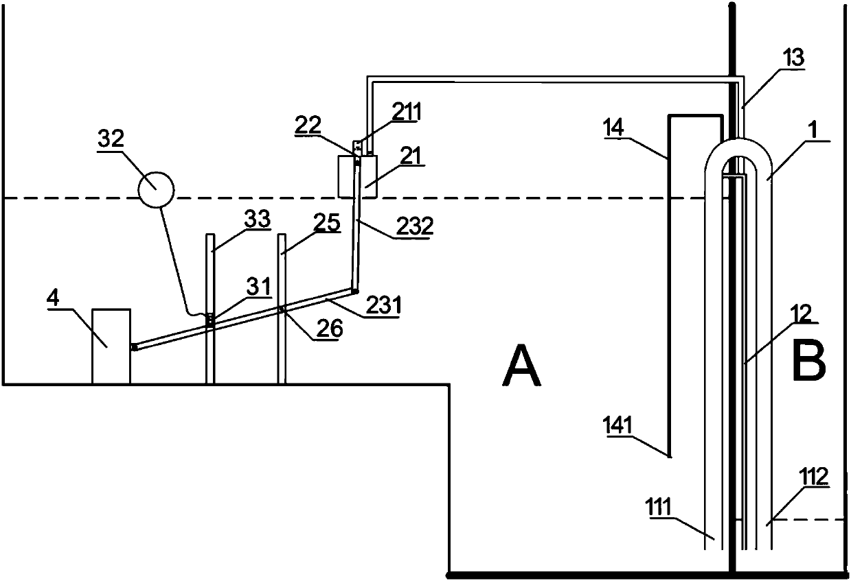
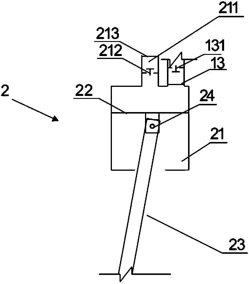
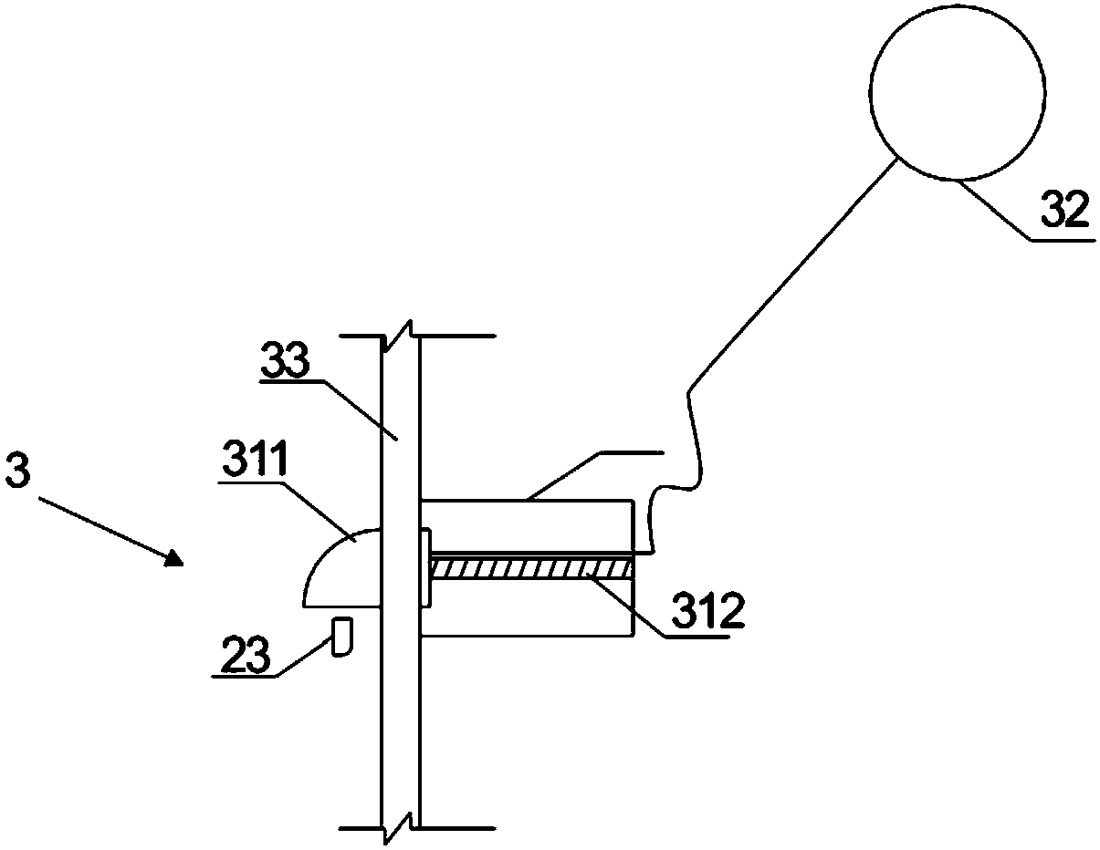
The invention provides a non-power automatic vacuum-pumping siphon auxiliary apparatus. The apparatus comprises a siphon, a vacuum device for exhausting gas in the siphon, and a control device for controlling the vacuum device to exhaust the gas. The vacuum device comprises a cylinder connected with the siphon, a piston arranged in the cylinder and a connecting rod for controlling the piston to move. The control device comprises a locking piece, a first floating ball for controlling opening and locking of the locking piece and a limiting member for supporting the connecting rod and limiting a rotation point. One end of the connecting rod limits a motion position through the opening or locking of the locking piece, and the other end is connected with the piston. According to the invention, the connecting rod rotates by taking the limiting member as a fulcrum, and the gas in the siphon is automatically exhausted through a lever principle. Under the condition that installation a power apparatus is unnecessary, the stability and the accuracy of the siphon are improved, the success rate is effectively improved, the structure is simpler, and the production cost is lower.

Description

technical field [0001] The invention relates to the technical field of water level control equipment, in particular to a non-powered automatic vacuum pumping siphon auxiliary device. Background technique [0002] Siphon is a force phenomenon that uses the difference in liquid level. After filling the liquid into an inverted U-shaped tubular structure, place the high end of the opening in a container filled with liquid. The liquid in the container will continue to pass through the siphon tube from the opening. flow out at a lower position. [0003] The current siphon auxiliary generation technology is used under the condition of a certain siphon water level, and in order to generate siphon, it is generally necessary to adopt auxiliary siphon measures on the siphon tube, and the measures are mainly divided into two types: one is to directly generate siphon through the siphon auxiliary tube Siphon; the other is to use a vacuum pump to assist vacuuming to generate a siphon. ...

Claims


Application Information

Patent Timeline
Patent Type & Authority Patents(China)
IPC IPC(8): G05D9/02
CPCG05D9/02
Inventor 汤岳洪德俊
Owner 上海碧兰环保技术开发有限公司
Why Eureka
Try Eureka