Gain automatic correction method and transmitter

An automatic calibration, transmitter technology, applied in gain control, transmission control/equalization, electrical components, etc., can solve the problems of gain control fluctuation, channel gain fluctuation, and inability to reflect power in real time, to overcome the average effect and achieve real-time The effect of gain correction

Active Publication Date: 2008-09-03
HUAWEI TECH CO LTD
View PDF0 Cites 25 Cited by
  • Summary
  • Abstract
  • Description
  • Claims
  • Application Information

AI Technical Summary

Problems solved by technology

However, due to the average effect of the output of the analog power detector, it cannot reflect the output power in real time
For example, in the Wimax system, the power of the preamble area and the data area are not equal. If an analog power detector is used to distinguish the power of the preamble area from the power of the data area, there will be errors in the gain control, and due to the averaging effect, when the power changes, It is also impossible to confirm whether it is caused ...

Method used


Image

  • Gain automatic correction method and transmitter
  • Gain automatic correction method and transmitter
  • Gain automatic correction method and transmitter

Examples


Embodiment 3

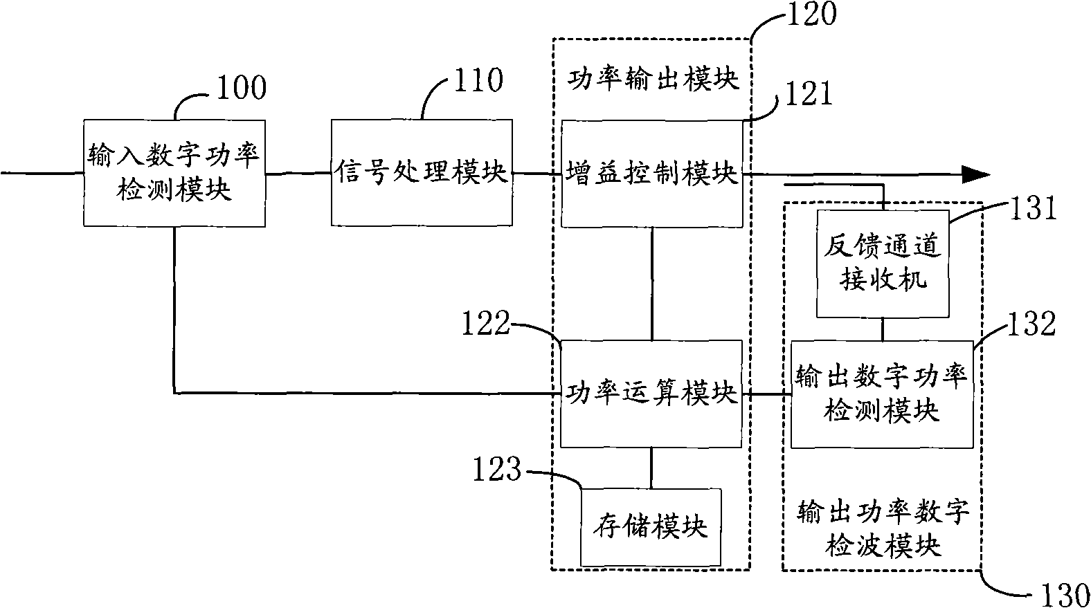
[0094] The transmitter correction parameter acquisition device described in the third embodiment, by setting the output power digital detection module and the output power analog detection module in the output section of the transmitter, the correction parameters obtained can effectively compensate for temperature changes and Transmitter power control errors caused by / or frequency changes (especially used to correct errors caused by the output power detection module being affected by temperature and / or frequency changes), to ensure that within the set frequency and / or within the set temperature range Consistency of output power.

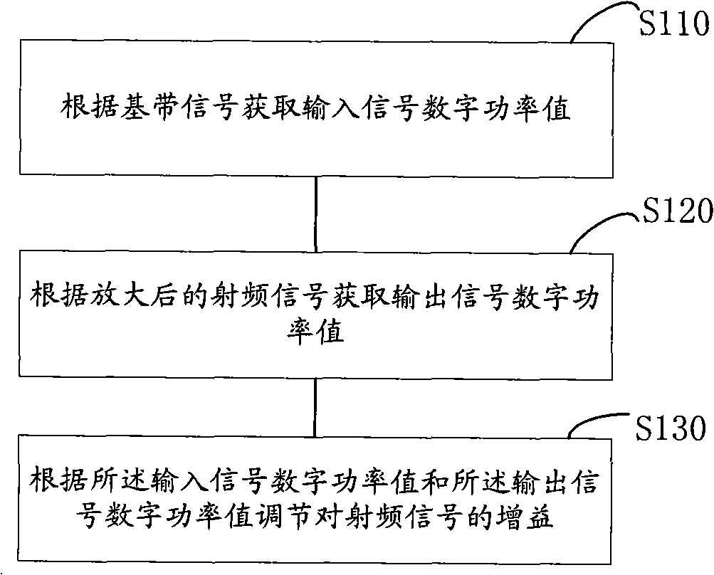
[0095] Embodiment 4 of the present invention relates to a method for acquiring correction parameters of a transmitter, such as Figure 4 shown, including the following steps:

[0096] S210: Obtain the digital power value of the output signal according to the radio frequency signal output by the transmitter;

[0097] Measuring the digital power valu...

Embodiment 4

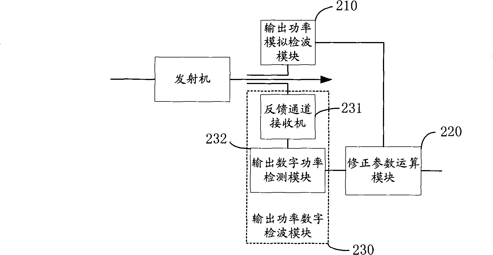
[0109] The method for obtaining correction parameters of the transmitter described in Embodiment 4 obtains the digital power value of the output signal and the analog power value of the output signal by performing digital detection and analog detection on the radio frequency signal output by the transmitter, and then obtains the correction parameters, which can effectively compensate for the Transmitter power control errors caused by temperature changes and / or frequency changes (especially used to correct errors caused by the output power detection module being affected by temperature and / or frequency changes), ensuring that the set frequency and / or set Consistency of output power over temperature.

[0110] The above embodiments of the present invention overcome the average effect of analog detection by adopting the digital detection of the feedback receiving channel at the output end of the transmitter, and can achieve the effect of real-time power detection, and further reali...


PUM


Abstract

The invention discloses a gain autocorrection sending machine, which comprises: an input digital power detection module for receiving the baseband signal, obtaining the incoming signal digital power based on the baseband signal; a signal processing module for processing the baseband signal from the input digital power detection module and outputting the radiofrequency signal, a power output module for magnifying and outputting the radiofrequency signal of the signal processing module, and regulating the gain of the radiofrequency signal based on the incoming signal digital power obtained by the input digital power detection module, the output signal digital power obtained by an output power digital detection module; the output power digital detection module for coupling the radiofrequency signal of the power output module, and obtains the output signal digital power based on the radiofrequency signal. The embodiment of the invention overcomes the average effect of the simulate detection in prior art, achieves the gain calibration in real time.

Description

technical field [0001] The invention relates to the field of communication technology, in particular to a gain automatic correction method and a transmitter. Background technique [0002] In the communication system, the downlink baseband signal enters the analog channel after being processed by the digital part, and after analog modulation, it is amplified by radio frequency and output to the antenna interface. The wireless characteristics such as the coverage of the base station require that the downlink channel must ensure a stable gain, so as to ensure that the antenna interface outputs a power equal to the expected power, thereby meeting the requirements of the wireless characteristics. However, the devices that make up the downlink channel (signal conversion, shaping filter, digital domain carrier combination, clipping, digital-to-analog conversion (DAC), IQ modulation, and up-conversion) will fluctuate due to factors such as device batches, temperature, and frequency....

Claims


Application Information

Patent Timeline
IPC IPC(8): H04B7/005
CPCH04W52/52H03G3/3042
Inventor 王晨韩富军徐红钢武杰
Owner HUAWEI TECH CO LTD
Why Eureka
Try Eureka