
Laser speckle blood flow imaging contrast analytical method

A laser speckle and analysis method technology, applied in medical science, diagnosis, diagnostic recording/measurement, etc., can solve problems affecting accurate blood flow assessment, limited time resolution of blood flow imaging, and uneven distribution of biological tissue absorption coefficients, etc. problem, to achieve accurate assessment of rapid changes, overcome the average effect, and reduce the effect of measurement error

Active Publication Date: 2013-09-25
HUAZHONG UNIV OF SCI & TECH
View PDF2 Cites 0 Cited by
  • Summary
  • Abstract
  • Description
  • Claims
  • Application Information

AI Technical Summary

Problems solved by technology

The former is obviously no longer suitable for blood flow imaging of fiber optic imaging systems; the latter, as a commonly used blood flow imaging analysis method for fiber optic imaging systems, has overcome the above problems, but its algorithm requires the use of image sequences composed of dozens of frames of images Contrast flow velocity analysis is performed, so the time resolution of blood flow imaging is limited, and the averaging effect of the time window will affect the accurate assessment of the rapid change process of blood flow
The lower time resolution in clinical applications often requires the subject to remain still for a long time, which does not meet the actual needs of the test
[0003] In addition, when performing spatial contrast analysis on speckle images collected directly by imaging lens groups (non-fiber optic imaging systems), due to factors such as uneven distribution of illumination light intensity and uneven distribution of biological tissue absorption coefficients, it is inevitable that there will be interference with the laser light. The Interference of Spatial Contrast Analysis in Speckle Blood Flow Imaging

Method used


Image

  • Laser speckle blood flow imaging contrast analytical method
  • Laser speckle blood flow imaging contrast analytical method
  • Laser speckle blood flow imaging contrast analytical method

Examples


Embodiment Construction

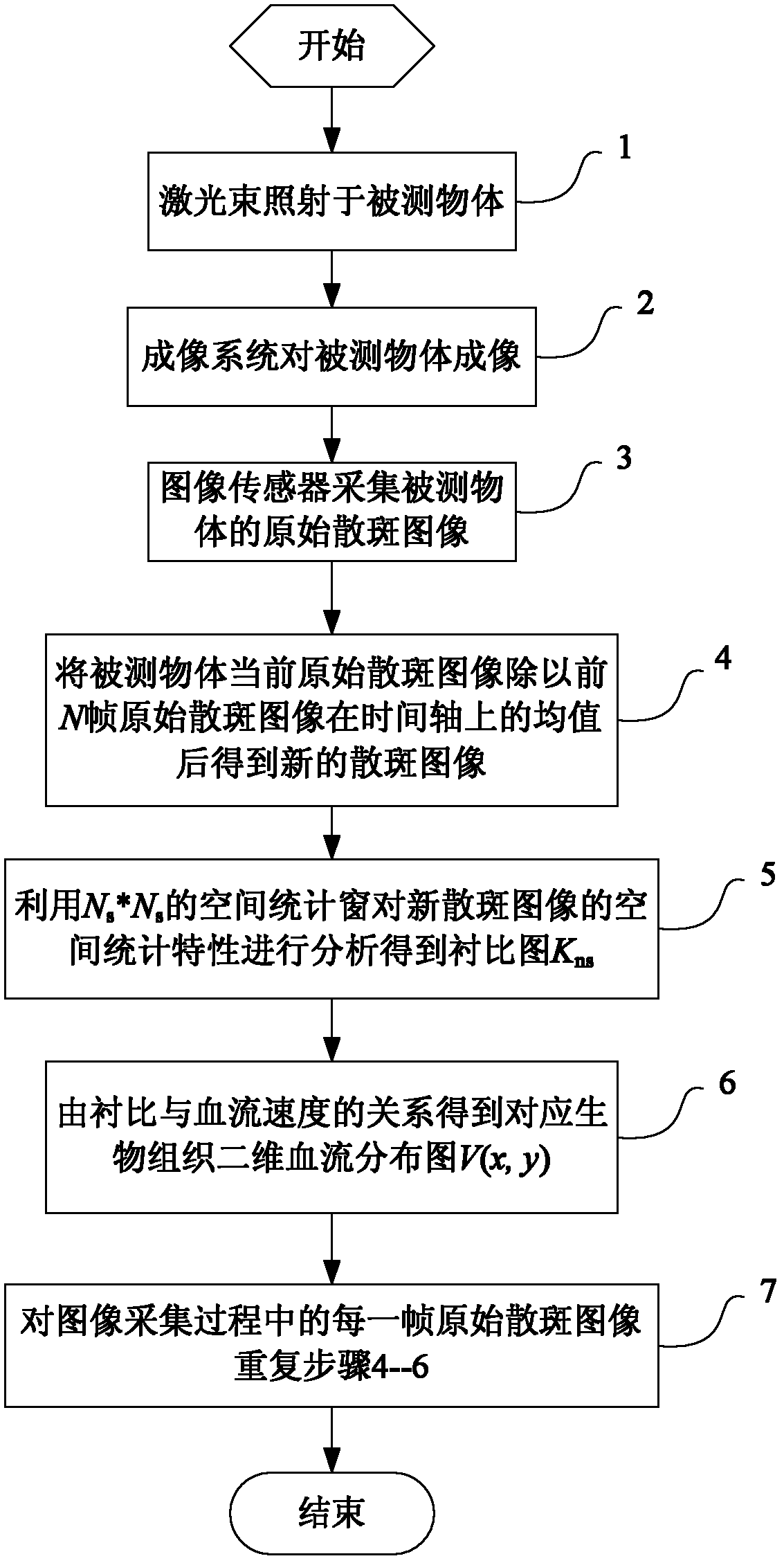
[0035] Such as figure 1 The algorithm flowchart of the laser speckle contrast analysis method shown in the present invention includes the following steps:

[0036] Step 1, irradiating the laser beam on the object to be measured;

[0037] Step 2, imaging the measured object by the imaging system;

[0038] Step 3, collecting the original speckle image of the measured object by the image sensor;

[0039] Step 4, using the formula (1) to process the collected original speckle image as follows:

[0040] I n ( x , y , p ) = I ( x , y , p ) I ave ( x , ...


PUM


Abstract

The invention discloses a laser speckle blood flow imaging contrast analytical method. The laser speckle blood flow imaging contrast analytical method comprises following steps that a laser beam illuminates a measured object, rear scattered light of the laser beam is collected by an imaging system and forms an image on an image sensor, after a current original speckle image of the measured object is divided by a mean value of a previous N-frame original speckle image on a time axis, so that a new speckle image is obtained, an Ns*Ns spatial statistic window analyzes spatial statistical property of the new speckle image so that a contrast image Kns is obtained, and a corresponding biological tissue two-dimensional blood flow distribution graph is obtained via the relation of contrast and blood flow speed. The laser speckle blood flow imaging contrast analytical method realizes accurate assess of local blood flow change, blood flow imaging and blood kinetic parameters of biological tissues in an endoscopic monitoring cavity at a high time resolution and low noise level, can be widely applied to dynamically monitoring blood flow distribution and change of insides of abdominal cavities of animals, insides of joints, stomach walls and the like, focus is positioned, pathological change of diseases are assessed, a medical effect is researched, and a higher clinical application value is realized.

Description

technical field [0001] The invention belongs to the field of biological tissue blood flow imaging methods, in particular to a laser speckle contrast analysis method. Background technique [0002] Laser speckle blood flow imaging technology has become an important means to study the temporal and spatial changes of blood flow in biological tissues under pathological / physiological conditions, and has been successfully applied to two-dimensional blood flow monitoring of the retina, skin, and cerebral cortex. Using optical fiber imaging system to transmit laser speckle images to realize endoscopic blood flow imaging in intracavitary tissue is an important trend and important application of this technology development. Blood flow imaging and evaluation of atherosclerotic plaque properties in the cardiovascular system. However, imaging fiber optic bundles are currently bonded by a large number of single fibers through a specific process. The inherent fiber gap and fiber cladding d...

Claims


Application Information

Patent Timeline
Patent Type & Authority Patents(China)
IPC IPC(8): A61B5/0265
Inventor 李鹏程骆清铭张红艳
Owner HUAZHONG UNIV OF SCI & TECH
Learn More