Method and device for correcting signal distortions in an amplifier device

A technology for amplifying equipment and signal distortion, applied in improving amplifiers to reduce nonlinear distortion, components of amplifying devices, amplifiers, etc., and can solve problems such as limited accuracy

Active Publication Date: 2006-01-04
APPLE INC
View PDF3 Cites 2 Cited by
  • Summary
  • Abstract
  • Description
  • Claims
  • Application Information

AI Technical Summary

Problems solved by technology

The disadvantage of this method is the limited accuracy, i.e. the minimum readjustment level is determined by the resolution of the PWM modulator
Furthermore, the disadvantage is

Method used


Image

  • Method and device for correcting signal distortions in an amplifier device
  • Method and device for correcting signal distortions in an amplifier device

Examples


Embodiment Construction

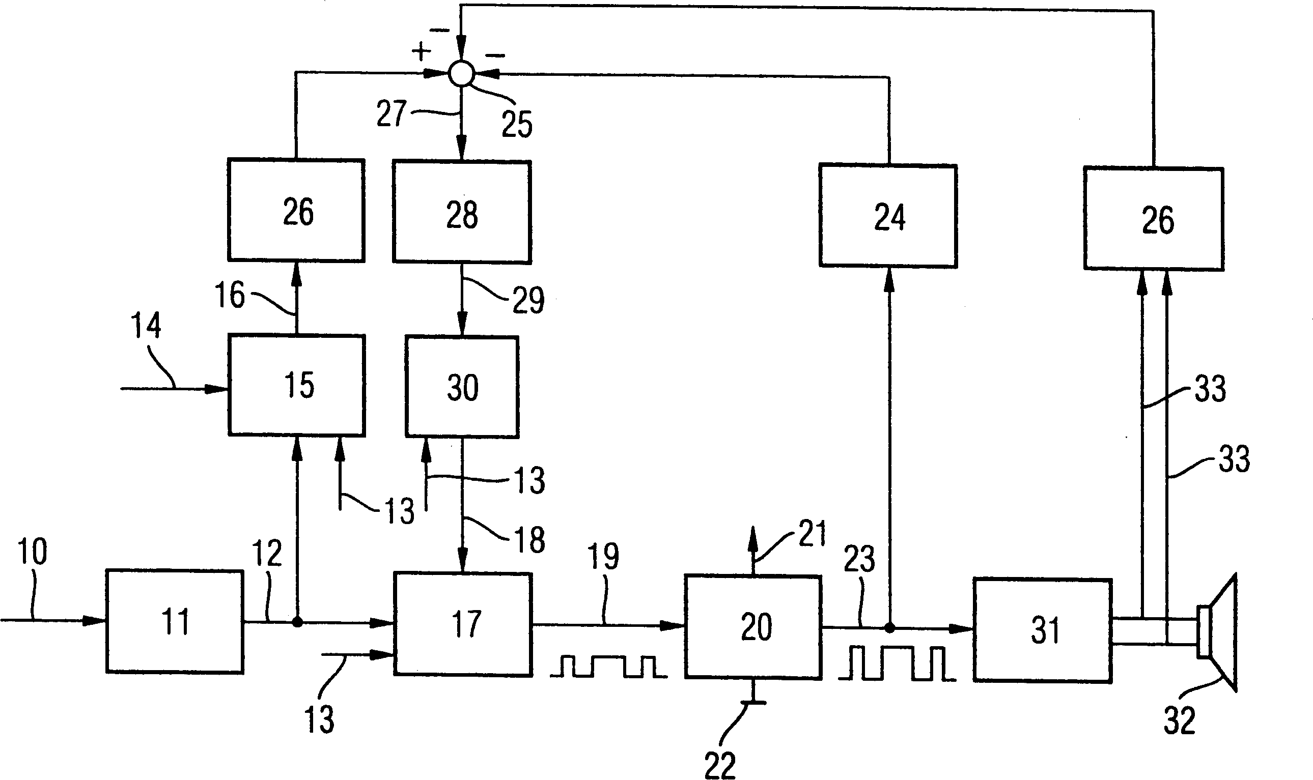
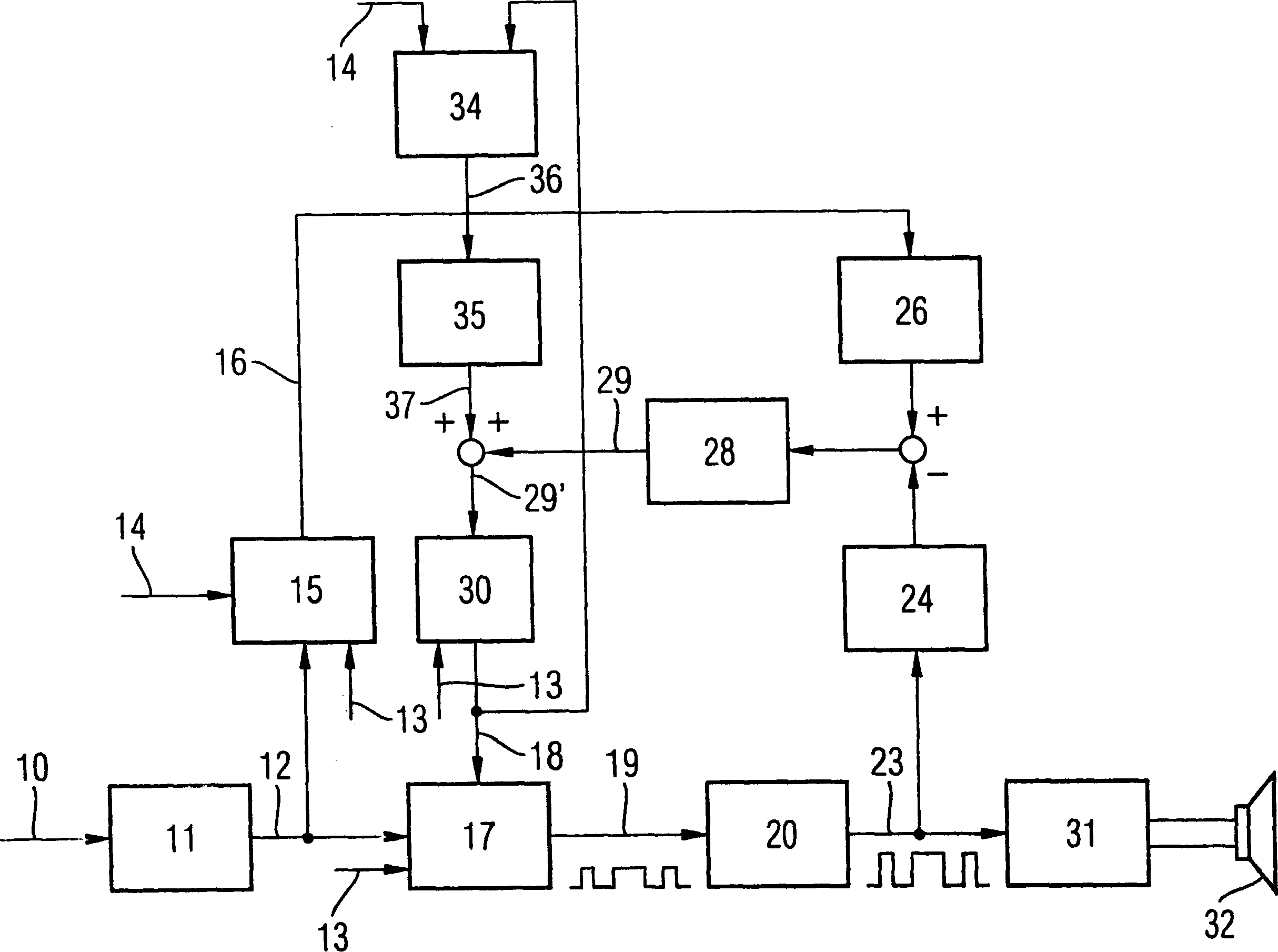
[0065] in accordance with figure 1 In the schematic block diagram of , the signal 10 (preferably a digital audio signal) is converted into PWM data or PWM information in a signal processing device 11, ie high-level pulse length and low-level pulse length in quantized form. Preferably, the signal processing device 11 is a digital circuit and calculates the PWM data 12 from the digital audio signal 10, preferably PCM encoded. Preferably, the PWM data 12 has the property that it is calculated in such a way that a quantized term of the pulse width information is calculated with every clock of the PWM pulse rate 13 . in accordance with figure 1 In the present exemplary embodiment, for example, the PWM pulse rate 13 is 288KHz, and the predetermined system clock 14 has a frequency of 88.128MHz.

[0066] A first PWM modulator 15 , which is controlled with a constant predetermined system clock 14 , generates a digital PWM reference signal 16 from the PWM data 12 . The constant prede...


PUM


Abstract

The invention relates to a method for correcting signal distortions in an amplifier device (20), which is characterized in that a digital PWM modulator (17) is operated with a frequency-variable clock (18). The invention also relates to a device for correcting signal distortions in an amplifier device (20).

Description

technical field [0001] The present invention relates to a method and device for correcting signal distortion in an amplifying device, and more particularly, to a method and device for correcting signal distortion of a driving circuit in a class D power amplifier. Background technique [0002] A pulse-width-modulated signal (PWM signal, pulse-width-modulated signal) has its signal information on the pulse width, not the signal information on the amplitude. Therefore, generally, a relay, a switching transistor, a thyristor or a triac, etc. are used to amplify the PWM signal. Thus, the switching device alternately switches the load between two potentials, typically a supply voltage and a reference potential (eg, ground), the duration of the on and off states being determined by the pulse width. [0003] However, this type of switch does not have ideal switching characteristics, ie, errors caused by the switch itself, such as switching delay, rise time and fall time (timing err...

Claims


Application Information

Patent Timeline
IPC IPC(8): H03F3/217H03F1/32
CPCH03F1/3247H03F3/217
Inventor 克里斯蒂安·克朗兹
Owner APPLE INC
Why Eureka
Try Eureka