
Demixing multi-ply non-collision high-efficiency energy dissipating construction for high arch dam body flood discharge of water gap district

A technology for high arch dams and energy dissipators, which is applied in water conservancy projects, sea area engineering, coastline protection, etc., and can solve problems such as the limitation of horizontal diffusion of arch dam flood discharge

Inactive Publication Date: 2008-09-24
BEIHANG UNIV
View PDF0 Cites 8 Cited by
  • Summary
  • Abstract
  • Description
  • Claims
  • Application Information

AI Technical Summary

Problems solved by technology

[0005] In order to alleviate the atomization problem caused by the collision of water tongues during flood discharge in the canyon area, and to solve the problem that the horizontal diffusion of arch dam flood discharge in the canyon area is severely limited, the present invention provides a flood distribution system for high arch dam body flood discharge in the canyon area. Layer multi-strand non-collision high-efficiency energy dissipation structure

Method used


Image

  • Demixing multi-ply non-collision high-efficiency energy dissipating construction for high arch dam body flood discharge of water gap district
  • Demixing multi-ply non-collision high-efficiency energy dissipating construction for high arch dam body flood discharge of water gap district
  • Demixing multi-ply non-collision high-efficiency energy dissipating construction for high arch dam body flood discharge of water gap district

Examples


Embodiment Construction

[0021] The present invention will be further described in detail below in conjunction with the accompanying drawings.

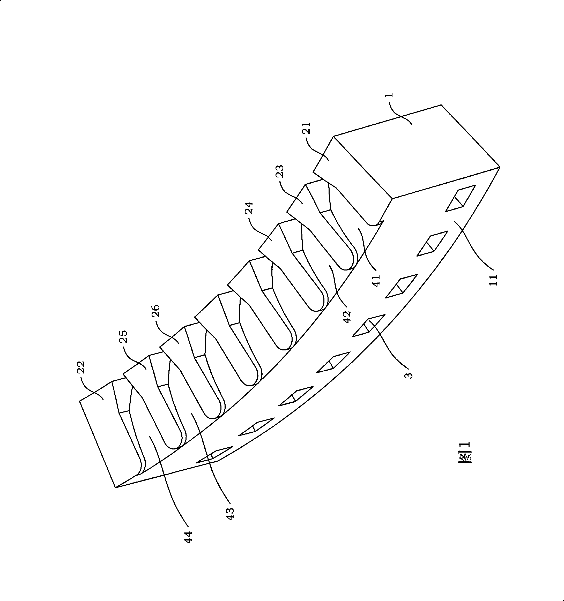
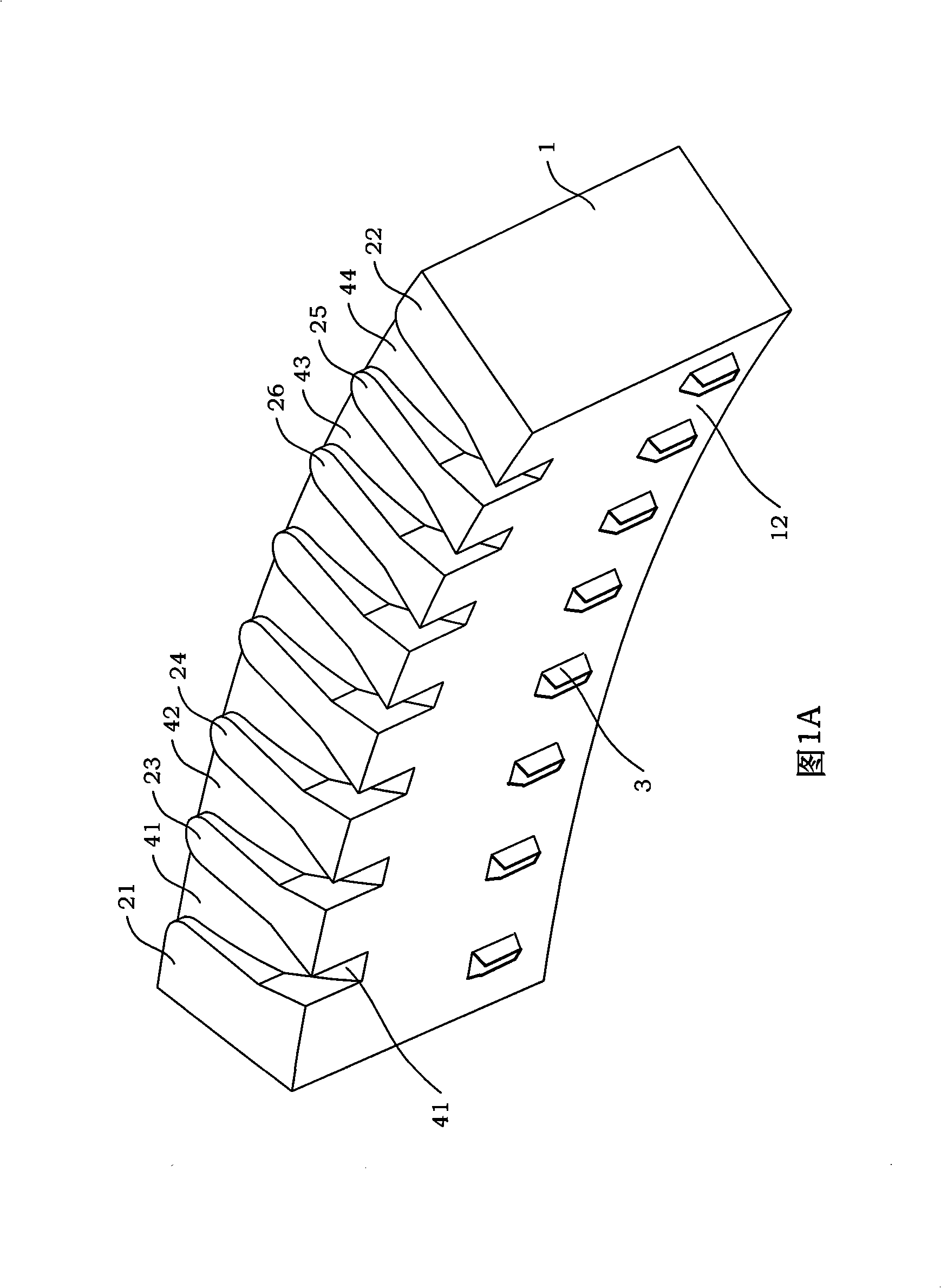
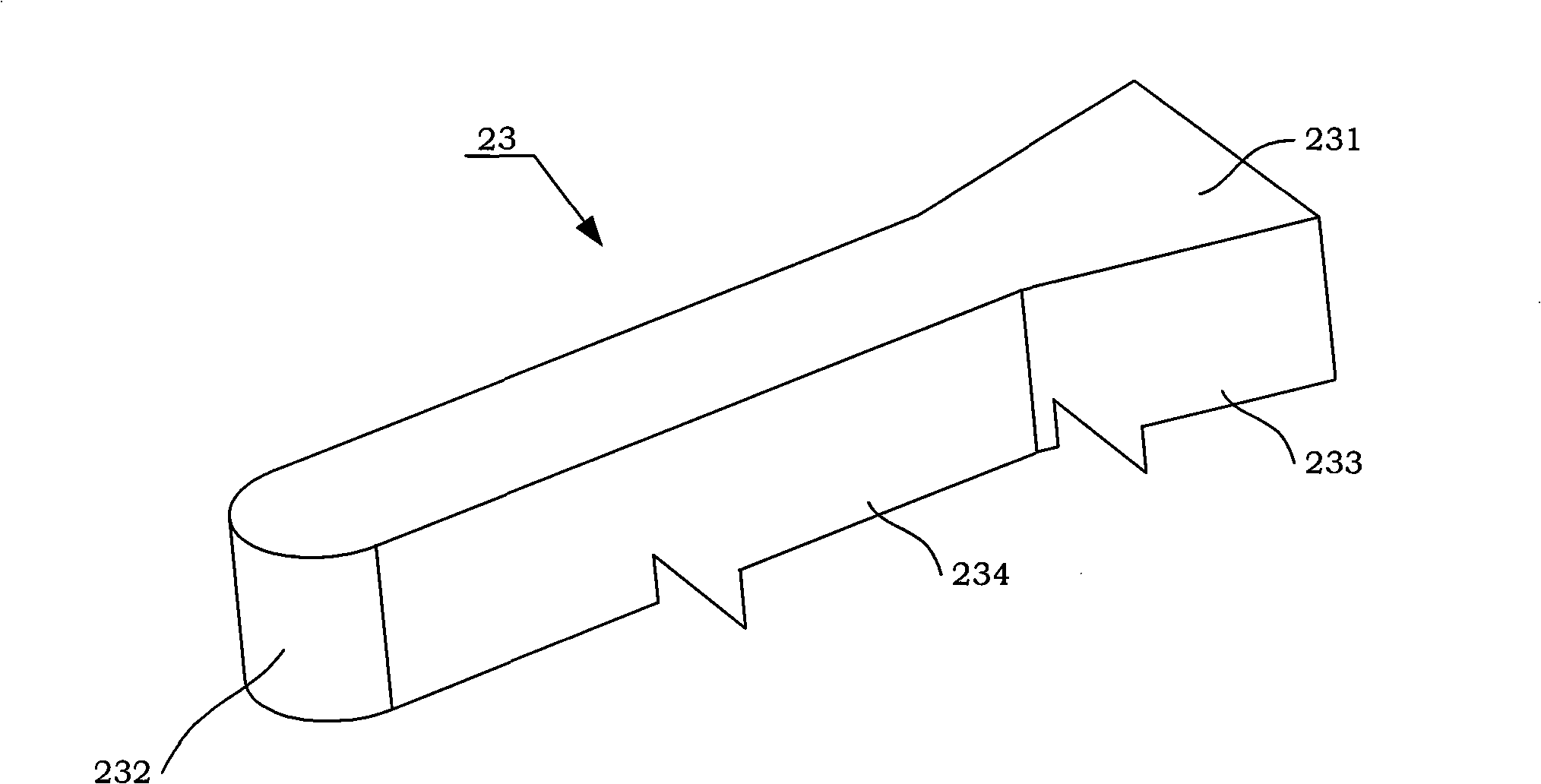
[0022] The invention is a layered multi-strand non-collision high-efficiency energy dissipation structure for flood discharge of high arch dams in canyon areas. The dam body of the high arch dam is provided with a plurality of deep holes and narrow sills. The design of the high arch dam flood discharge method with wide tail piers and deep holes and narrow sills is conducive to the full spread of the water tongue in the vertical and longitudinal directions to adapt to the narrow valley terrain; two adjacent surface holes are wide A surface hole overflow channel is formed between the tail piers, and the downflow is subjected to the lateral contraction of the surface hole overflow channel, so that the surface hole water tongue forms a narrow sheet-like jet; The lateral contraction of the slit ridge makes the deep hole water tongue form a narrow thin sheet jet. ...


PUM


Abstract

The invention discloses a layered multistrand noncollision effective dissipater structure used for the flood discharge of a high dam body in a gorge area which adopts surface spillway tail-flaring piers and deep hole narrow ridges to combine for flood discharge. The effective dissipater structure arranges a plurality of surface spillway tail-flaring piers on the top of a high arch dam; surface spillway flooding channels are arranged between neighboring tail-flaring piers so as to form a surface spillway longitudinal diffusing water flow; a plurality of deep hole narrow ridges are arranged at the one second or two third location of the height of the high arch dam; the jet flow outlets of the deep hole narrow ridges are staggered with the jet flows of the surface spillways. A straight section and a dispersing section are arranged between the tail and the head of the piers; the dispersing angle of the dispersing section relative to the straight section Theta is equal to arctan(b0-b) / 2l; in the relevant position coordinate between the crossing point A of the line of intersection of the straight section and the dispersing section and the flooding weir surface of the flooding channel, and the shaping design water head Hd of the flooding weir surface, Xi x is equal to x0Hd and Xi y is equal to y0Hd. The straight section and a shrinking section are arranged between the water flow inlet and the water flow outlet of the narrow ridges; the shrinking angle of the shrinking section relative to the straight section Beta is equal to 12 to 15 degrees; the ratio of the width d of the water flow outlet and the width D of the water flow inlet should meet 0.3 to 0.7.

Description

technical field [0001] The invention relates to a layered multi-strand non-collision high-efficiency energy dissipation structure used for flood discharge of high arch dams in canyon areas, which is a structure applied to dam heights of 200-300m, high water heads, and large flow rates of 30-50m / s , Large flow rate 10000~50000m 3 / s, the river valley is narrow, and the single-width flow rate is 100-300m 3 / s m high arch dam flood discharge energy dissipation. Background technique [0002] The main problems encountered in the flood discharge and energy dissipation of high arch dams in the canyon area are: narrow river channels, high water heads, large discharge volumes, and concentrated jet water tongues, which cause considerable difficulty in the design of energy dissipation and anti-scour under the dam. In order to effectively reduce the dynamic water impact pressure of the discharge tongue on the bottom plate of the cushion pond, it is necessary to diffuse the discharge f...

Claims


Application Information

Patent Timeline
Patent Type & Authority Applications(China)
IPC IPC(8): E02B8/06
Inventor 刘沛清焦爱萍原平新钮本良张春满
Owner BEIHANG UNIV
Learn More