
Joint box sealing device adopting screw cap rotating impacted sealing ring automatic enclasping optical fibre cable

A technology of compression sealing and sealing device, which is applied in the direction of cable entry sealing device, cable installation, optical waveguide coupling, etc. It can solve the problems of shortened service life of the joint box, inconvenient construction and expansion, and poor sealing performance, etc., to achieve Long-term reliable sealing, ensuring long-term safe operation, and ensuring the effect of sealing performance

Inactive Publication Date: 2008-09-24
茹志康
View PDF0 Cites 18 Cited by
  • Summary
  • Abstract
  • Description
  • Claims
  • Application Information

AI Technical Summary

Problems solved by technology

[0009] The purpose of the present invention is to provide a joint box sealing device that uses the nut to rotate and compress the sealing ring to automatically hold the optical cable tightly, so as to solve the problems existing in the existing optical cable sealing technology, resulting in shortened service life of the joint box, inconvenient construction and expansion, and poor sealing performance. Poor, can not prevent termites and other issues

Method used


Image

  • Joint box sealing device adopting screw cap rotating impacted sealing ring automatic enclasping optical fibre cable
  • Joint box sealing device adopting screw cap rotating impacted sealing ring automatic enclasping optical fibre cable
  • Joint box sealing device adopting screw cap rotating impacted sealing ring automatic enclasping optical fibre cable

Examples


Embodiment Construction

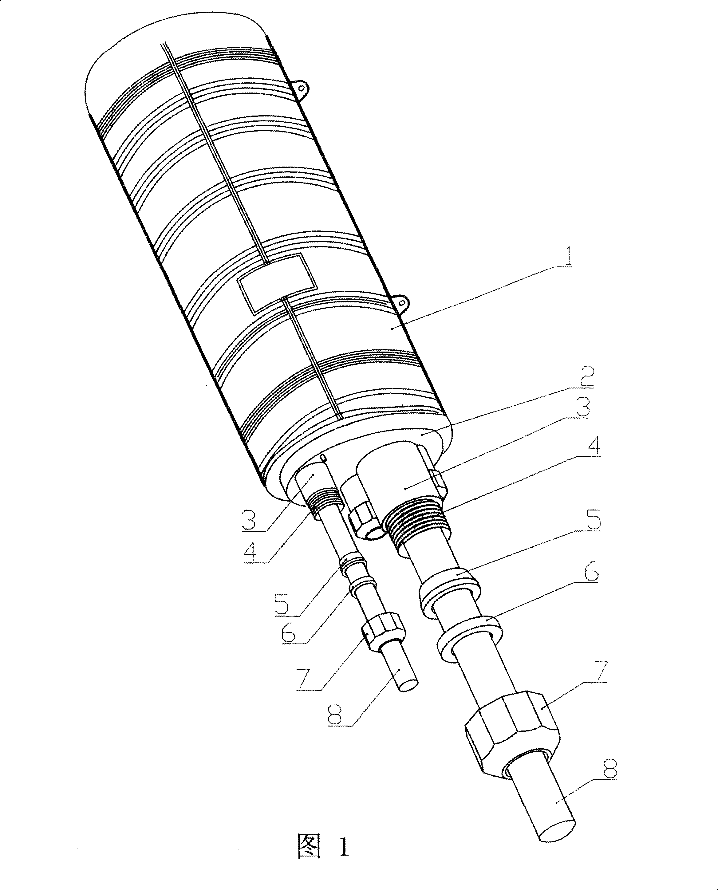
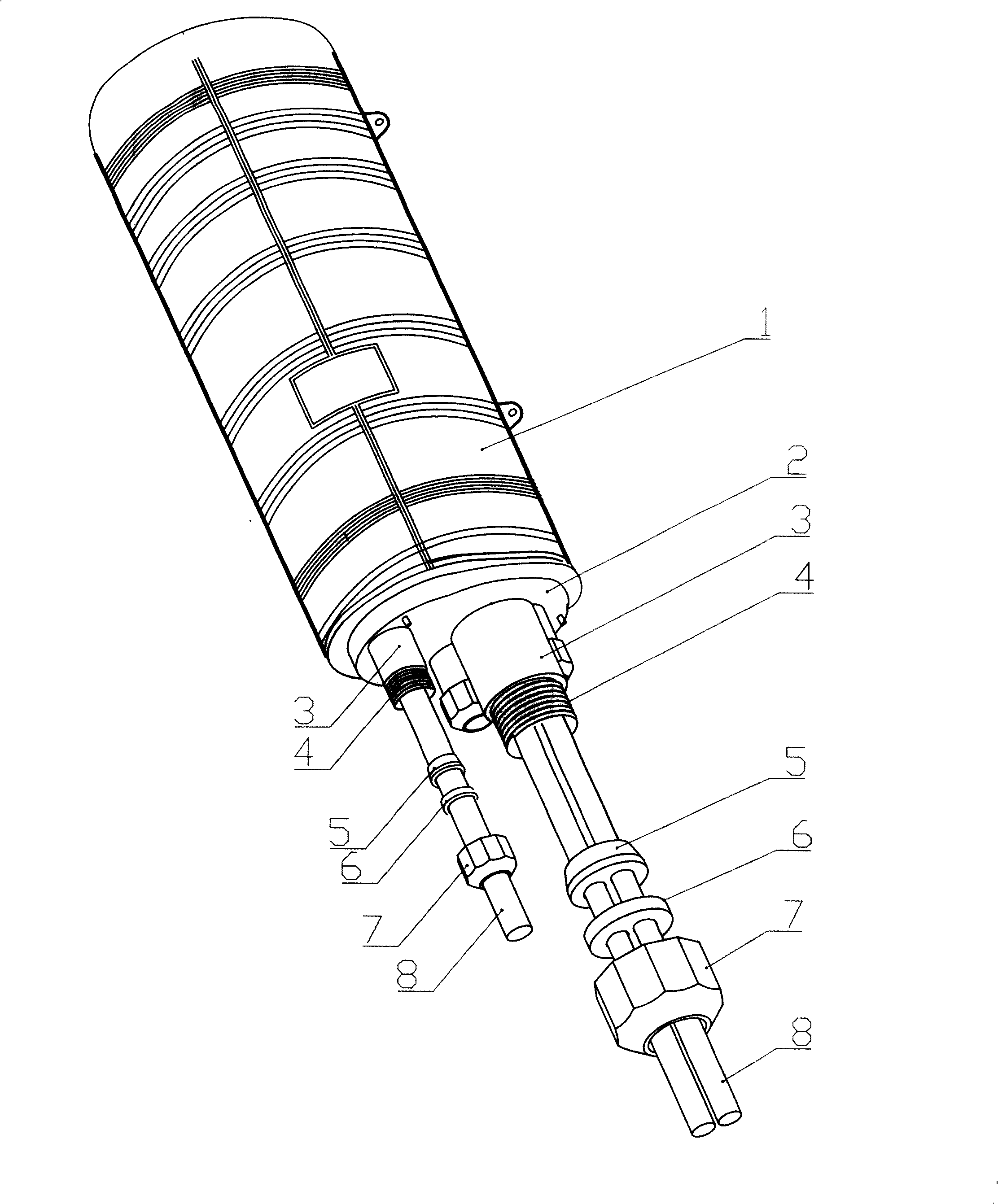
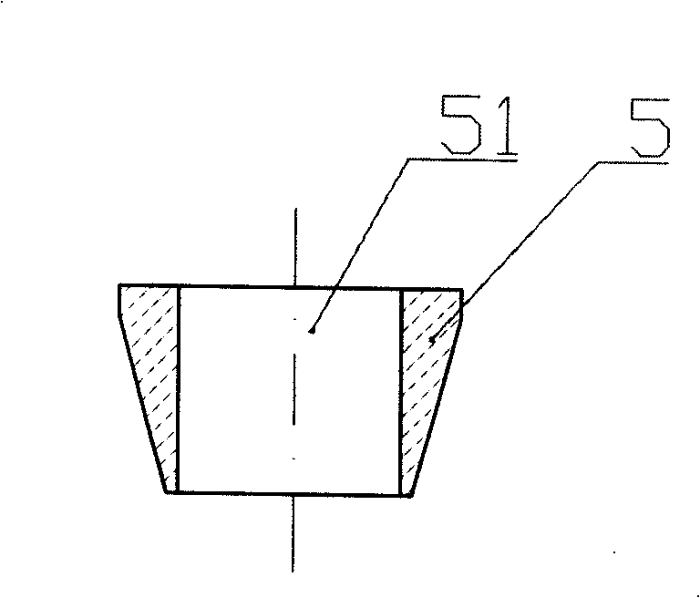
[0054] See Figure 1~ Figure 37 , the basic structure of the present invention comprises optical cable inlet and outlet pipe 3, nut 7, plastic washer 6 and elastomer seal ring 5, and described optical cable inlet and outlet pipe 3 is on the box bottom 2 of optical cable connector box body 1, and the optical cable inlet and outlet pipe 3 An external thread 4 is provided on the outside, and the nut 7 is provided with an internal thread matching the external thread 4. When assembling, the optical cable 8 is passed through the cable hole of the nut 7, the plastic gasket 6 and the cable hole of the elastomer sealing ring 5 in sequence. , and then tighten the nut 7 on the external thread 4 of the cable inlet and outlet tube 3, so that the inlet and outlet cables can be tightened and sealed, and the installation and operation are convenient. The positions of the optical cable hole of the plastic gasket 6 and the optical cable hole of the elastomer sealing ring 5 correspond to each ot...


PUM


Abstract

A connector box sealing device which adopts a nut rotary compression sealing ring to automatically tightly hold an optical fiber cable, comprising a box bottom of an optical fiber cable connector box, an optical fiber cable inlet and outlet pipe which is arranged on the box bottom, a nut, a plastic washer and an elastomer sealing ring, the exterior of the optical fiber cable inlet and outlet pipe and the interior of the nut are both provided with threads which are mutually matched, the optical fiber cable sequentially penetrates the nut, the plastic washer and an optical fiber cable hole which is corresponding by the elastomer sealing ring, and then the nut is screwed to carry out the fastening and sealing of the getting-in and out optical fiber cable. The optical fiber cable inlet and outlet pipe, the nut and the plastic washer of the invention can play the protection role of the elastomer sealing ring which is arranged in the optical fiber cable inlet and outlet pipe, the elastomer sealing ring can not be bitten by termites absolutely, so the sealing mode has the function of preventing the termites, convenient installation and long-term reliable sealing, while the optical fiber cable and the optical fiber network can be further ensured to be operated safely for a long time.

Description

technical field [0001] The invention relates to a protection device for the connection point of the optical fiber network of the optical cable and the distribution point of the optical cable, in particular to an innovative sealing structure in which the optical cable joint box is installed with an optical cable seal and adopts a screw cap to rotate and compress the sealing ring to automatically hold the optical cable tightly, and is suitable for pairing of the optical cable joint box The tight sealing of the optical cable in and out is convenient for installation and reliable for long-term sealing. Background technique [0002] Most of the optical cable splice boxes at home and abroad now use the method of heating the optical cable heat-shrinkable sleeve and winding the sealing tape to seal the optical cable inlet and outlet parts. There are many disadvantages in this sealing method: [0003] 1. Before installing the optical cable, the optical cable inlet and outlet tubes o...

Claims


Application Information

Patent Timeline
IPC IPC(8): G02B6/38G02B6/44
CPCG02B6/4454G02B6/4444H02G15/013H02G15/115G02B6/44775
Inventor 茹志康
Owner 茹志康
Learn More