
Electromagnetic device with displaceable connections

A technology of equipment and wiring parts, applied in electromagnetic relays, electromagnetic relay details, circuits, etc., can solve problems such as unclearness, wiring errors, and difficulty in accessing protective relays, and achieve the effect of avoiding wiring errors

Inactive Publication Date: 2010-12-22
SIEMENS AG
View PDF7 Cites 0 Cited by
  • Summary
  • Abstract
  • Description
  • Claims
  • Application Information

AI Technical Summary

Problems solved by technology

This leads to the fact that the feeder lines of the terminal units have to be routed over the protective relay, which is not clear, makes it difficult to reach the protective relays and can lead to wiring errors, especially in the case of several terminal units

Method used


Image

  • Electromagnetic device with displaceable connections
  • Electromagnetic device with displaceable connections
  • Electromagnetic device with displaceable connections

Examples


Embodiment Construction

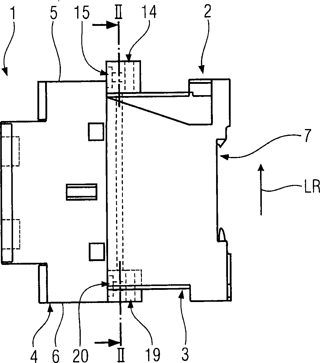
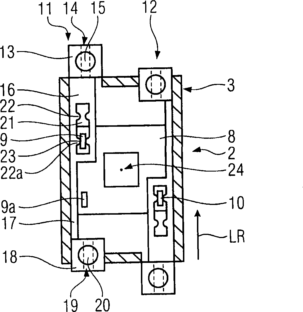
[0023] Next, refer to Figure 1 to Figure 4 The embodiments of the present invention will be described. The electromagnetic switchgear, protective relay 1 has a housing 2 with a longitudinal direction LR. The housing 2 has a length L in the longitudinal direction LR G . The housing 2 is made of insulating material, especially plastic. The housing 2 includes a housing lower part 3 and a housing upper part 4 detachably connected to it. In the longitudinal direction LR, the housing 2 is defined by a first end side 5 and a second end side 6 opposite to the first end side. The lower part of the housing 3 has a specially designed fixing vacancy 7 for fixing the housing 2 on a fixed rail designed for this purpose, not shown.

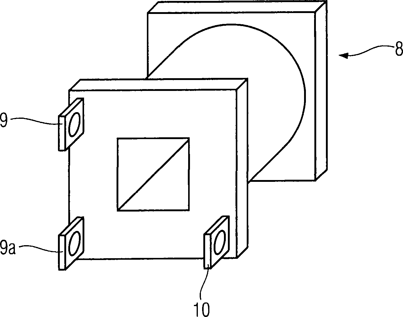
[0024] in image 3 The coil 8 shown in FIG. 1 and having the first coil contact 9 and the second coil contact 10 is immovably arranged in the housing lower part 3. According to figure 2 In the embodiment shown in the coil 8 is designed as a three-leg coil wit...


PUM


Abstract

The invention relates to electromagnetic equipment with a mobile connection box. The equipment includes: a shell body (2) having a length in a longitudinal direction (LR), a first end side vertical to the longitudinal direction (LR) and a second end side relative to the first end side vertical to the longitudinal direction (LR); a control coil (8) installed in the shell body (2) used for operating an electric switch with a first and a second coil contact terminals (9, 10); a first and a second connection elements (11, 12) partially installed inside the shell body (2), wherein, the connection elements (11, 12) can move between the first end position and the second end position relative to the shell body in the longitudinal direction (LR) in such a manner that these connection elements can freely contact an end side at the first end position and can freely contact the other end side at the second end position, and the first end position and the second end position are electrically connected with the belonging coil contact terminals (9, 10).

Description

Technical field [0001] The invention relates to an electromagnetic switch device for controlling branch circuits. Background technique [0002] In the prior art, electromagnetically operated switches and protective relays used to close and disconnect the main circuit with the greatest possible power consumption are disclosed. Here, a magnetic field is generated by the current flowing through the coil, and mechanical electrical contact is realized by the magnetic field, and the electrical contact closes or opens the main circuit. The protection relay is often combined with a motor protection switch, an overload relay or a safety device in a switch device, but it can also be used alone. Usually, the position of the wiring device on the protective relay is fixedly predetermined by the manufacturer. This results in that the feeder line of the wiring device must be guided on the protective relay, which is unclear, making it difficult to reach the protective relay, and especially in ...

Claims


Application Information

Patent Timeline
Patent Type & Authority Patents(China)
IPC IPC(8): H01H50/14
CPCH01H50/443H01H11/0031H01H50/14
Inventor 格奥尔格·博林格约翰·德雷克斯勒
Owner SIEMENS AG
Learn More