Diode absorption circuit for bridge rectifier circuit

A technology of absorption circuit and diode, applied in the field of electronics, can solve the problem of large loss of absorption resistance R1, etc.

Active Publication Date: 2011-06-29
O&C ELECTRIC TECHN CO LTD
View PDF0 Cites 0 Cited by
  • Summary
  • Abstract
  • Description
  • Claims
  • Application Information

AI Technical Summary

Problems solved by technology

[0004] The disadvantage of the traditional snubber circuit is that the loss on the snubber resistor R1 is quite large, and the snubber resistor R1 should use a larger power resistor

Method used


Image

  • Diode absorption circuit for bridge rectifier circuit
  • Diode absorption circuit for bridge rectifier circuit
  • Diode absorption circuit for bridge rectifier circuit

Examples


Embodiment 1

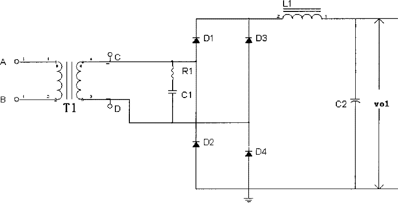
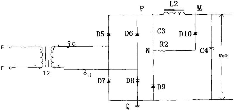
[0023] Diode snubber circuits used in bridge rectifier circuits such as image 3 As shown, the diode snubber circuit is composed of C3, D9, R2, and D10. C3 is generally a non-inductive absorbing capacitor between 1nF and 10nF, and R2 is generally a absorbing resistor ranging from 10 ohms to 100 ohms. D9 and D10 cooperate with C3 and R2 to complete the absorbing function. L2 is a filter inductor, which together with the filter capacitor C4 completes the smooth filtering of the pulsating voltage after bridge rectification on the secondary side of the transformer to ensure that the output voltage Vo2 is a smooth DC.

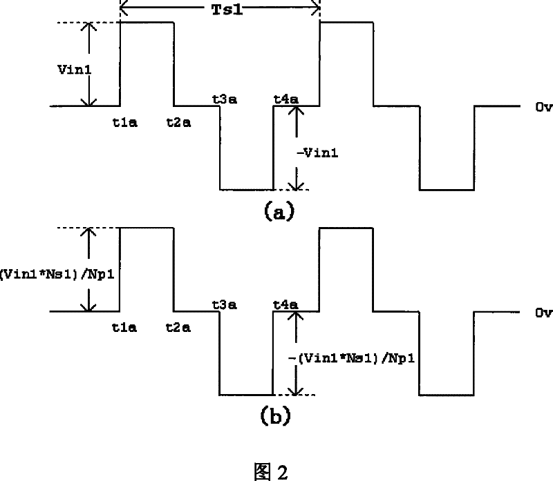
[0024] In this example, the primary and secondary voltage waveforms of the transformer T2 are shown in Figure 4.

[0025] The advantage of the diode snubber circuit in this example is that the loss on the resistor R2 is smaller than that of the traditional circuit, and the snubber effect is almost the same. The specific analysis is as follows:

[0026] Such as ...


PUM


Abstract

The invention discloses a diode absorbing circuit in bridge type rectification circuit, which comprises a rectification bridge, an inductance (L2) and a first capacitance (C4), one end of the inductance (L2) is connected with an output end (P) of the rectification bridge, the other end (M) is connected with the positive pole of the first capacitance (C4), the negative pole of the first capacitance (C4) is connected with the other output end (Q) of the rectification bridge, the diode absorbing circuit also comprises a second capacitance (C3), a resistance (R2), a first diode (D9) and a second diode (D10); one end of the second capacitance (C3) is connected with an output end (P) of the rectification bridge, the other end is connected with the negative pole of the first diode (D9), the positive pole of the first diode (D9) is connected with the other output end (Q) of the rectification bridge; one end of the resistance (R2) is connected with the negative pole of the first diode (D9), the other end is connected with the positive pole of the second diode (D10). The diode absorbing circuit in bridge type rectification circuit can evidently reduce the energy consumption of dead resistance in the bridge type rectification circuit.

Description

technical field [0001] The invention belongs to the field of electronic technology and relates to a diode absorbing circuit used in a bridge rectifier circuit. Background technique [0002] In a switching power supply with high voltage output, if the output voltage is greater than 100V, the secondary output is often used in a bridge rectifier circuit. Due to the existence of transformer leakage inductance, the diode will generate a high voltage spike when it is turned off, and the excessive voltage The spike will damage the diode, so a spike suppression circuit is often added to absorb the voltage spike to protect the diode. [0003] In the traditional bridge conversion circuit, the conventional voltage spike suppression circuit (that is, the diode snubber circuit) is to add an RC resistance-capacitance snubber circuit to the secondary winding of the transformer. Traditional diode snubber circuits such as figure 1 R1 and C1 in the circuit shown. In a traditional bridge co...

Claims


Application Information

Patent Timeline
Patent Type & Authority Patents(China)
IPC IPC(8): H02M7/06H02M1/32
Inventor 赵林冲汤世娟
Owner O&C ELECTRIC TECHN CO LTD
Why Eureka
Try Eureka