
Electronic blood pressure monitor

An electronic sphygmomanometer and blood pressure value technology, applied in vascular assessment, cardiac catheterization, etc., can solve the problems of exhaust valve difficulty, inability to obtain the minimum blood pressure value, and compression of upper arm length, etc., to achieve the effect of shortening the time

Active Publication Date: 2008-10-29
CITIZEN WATCH CO LTD
View PDF1 Cites 2 Cited by
  • Summary
  • Abstract
  • Description
  • Claims
  • Application Information

AI Technical Summary

Problems solved by technology

[0009] As mentioned above, in the conventional electronic sphygmomanometer, the two-mountain countermeasure has been studied, and since the measurement is continued after the minimum blood pressure value is determined until the predetermined cuff pressure is reached, there is a problem that the time for compressing the upper arm, etc. is prolonged.
In particular, when the user is hypertensive, the measurement will continue for a long time after the lowest blood pressure value is determined, so there is a problem that the upper arm is pressed for a long time.
[0010] Also, in the electronic sphygmomanometer disclosed in Patent Document 1, there is a cuff that adds a predetermined value to the cuff pressure when the maximum pulsation wave occurs from the cuff pressure point obtained by subtracting the predetermined value from the estimated maximum blood pressure value. When there is a real minimum blood pressure value during the rapid decompression up to the pressure point, the real minimum blood pressure value cannot be obtained
Furthermore, in the electronic sphygmomanometer disclosed in Patent Document 1, during the decompression process, it is extremely important to correctly adjust the opening of the exhaust valve of the cuff according to the mode of decompression from slow decompression to rapid decompression and then back to slow decompression. difficult
Therefore, the electronic sphygmomanometer disclosed in Patent Document 1 lacks realizability

Method used


Image

  • Electronic blood pressure monitor
  • Electronic blood pressure monitor
  • Electronic blood pressure monitor

Examples


Embodiment Construction

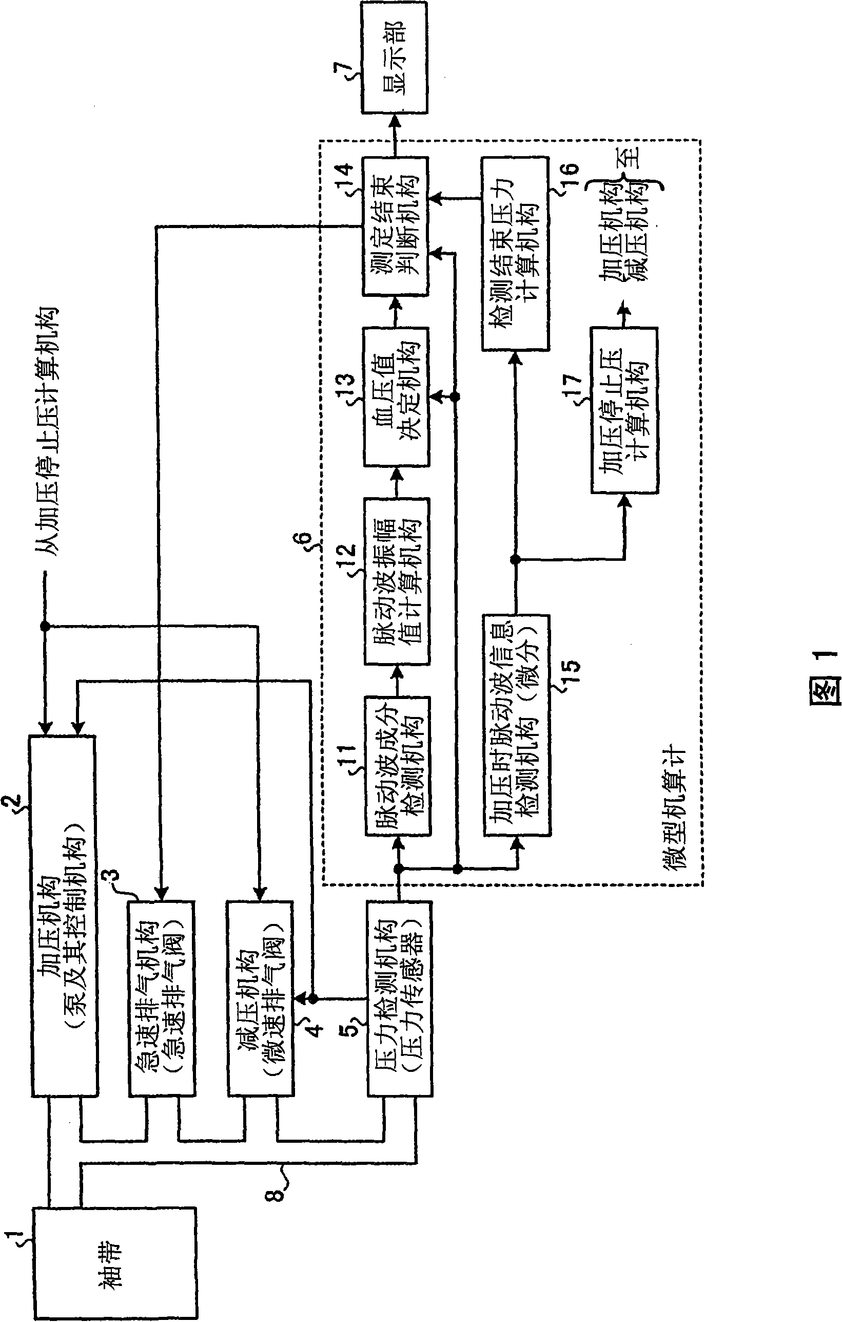
[0034]Hereinafter, preferred embodiments of the electronic sphygmomanometer according to the present invention will be described in detail with reference to the drawings. FIG. 1 is a block diagram showing the configuration of an electronic sphygmomanometer according to an embodiment of the present invention. As shown in FIG. 1 , the electronic sphygmomanometer includes a cuff 1 ; a pressurization mechanism 2 ; a rapid exhaust mechanism 3 ; a decompression mechanism 4 ; a pressure detection mechanism 5 ; The cuff 1 is connected with the pressurizing mechanism 2 , the rapid exhaust mechanism 3 , the decompression mechanism 4 and the pressure detection mechanism 5 through a conduit 8 .

[0035] The pressurization mechanism 2 rapidly pressurizes the cuff 1 according to the output signal of the pressure detection unit 5 , and is controlled so that pressurization is stopped by the pressurization stop pressure calculation unit 17 . The pressurizing mechanism 2 is constituted by, for...


PUM


Abstract

An electronic sphygmomanometer is provided, in accordance with pulsating wave information at the time of pressurizing a cuff (1), finishing pressure is measured by a finishing pressure measurement mechanism (16). In the process of decompression, in case that a blood pressure deciding mechanism (13) decides the cuff pressure at the time of the minimum value of blood pressure is lower than the measured finishing pressure, a finishing measurement judging mechanism (14) judges the finish of the measurement and a quick-speed exhausting mechanism (3) exhausts quickly to the cuff (1) at once. In case that the cuff pressure at the time of the minimum value of blood pressure is not lower than the measured finishing pressure, the measurement is continued, and is finished when the cuff pressure is altered to be lower than the measured finishing pressure, then the quick-speed exhausting mechanism (3) exhausts quickly to the cuff (1) at once. Consequently, in the electronic sphygmomanometer, the fluids in the cuff are enabled to exhaust rapidly and quickly after correctively deciding the minimum value of blood pressure, thereby shortening the pressing time on the upper arms.

Description

technical field [0001] The present invention relates to an electronic sphygmomanometer for measuring blood pressure by an oscillometric (Oscillometry) method. Background technique [0002] FIG. 7 is a characteristic diagram showing an example of variation in cuff (cuff, cuff) internal pressure (hereinafter referred to as cuff pressure) during blood pressure measurement. As shown in FIG. 7 , when the blood pressure is measured by the oscillometric method, during the decompression process of gradually reducing the cuff pressure, pulsation appears as a change in the cuff pressure. Based on the measurement result of this pulsation, the maximum blood pressure value and the minimum blood pressure value are determined. [0003] FIG. 8 shows a pulse wave (pulse wave) extracted by subtracting the amount of decrease in cuff pressure from the amount of fluctuation in cuff pressure during the decompression process based on the characteristic diagram shown in FIG. 7 with the horizontal ...

Claims


Application Information

Patent Timeline
Patent Type & Authority Applications(China)
IPC IPC(8): A61B5/022
Inventor 中西孝伊藤清
Owner CITIZEN WATCH CO LTD
Learn More