High-voltage transformer
A high-voltage transformer and winding technology, applied in the field of high-voltage transformers, can solve the problems of adjustment error and difficult fine adjustment of leakage inductance
- Summary
- Abstract
- Description
- Claims
- Application Information
AI Technical Summary
Problems solved by technology
Method used
Image

Examples
no. 1 approach
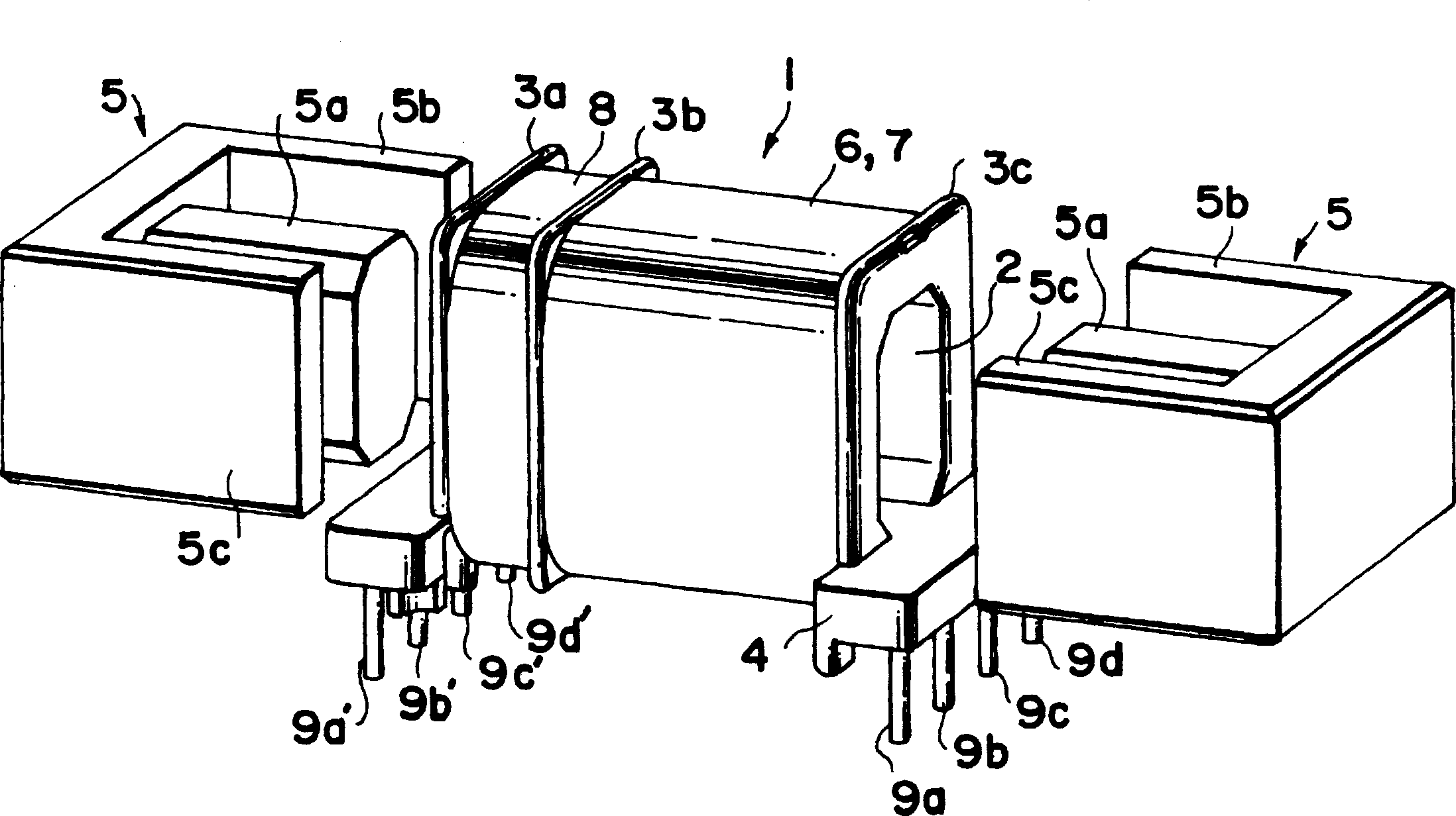
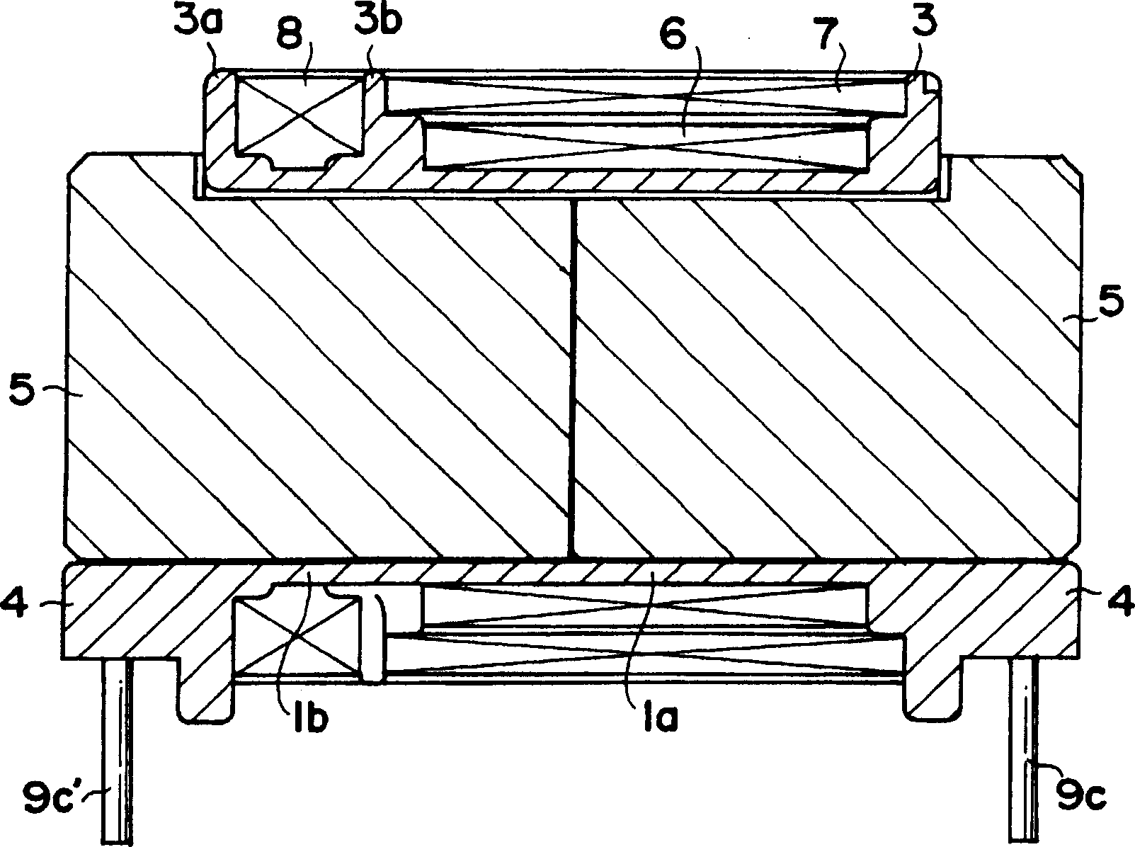
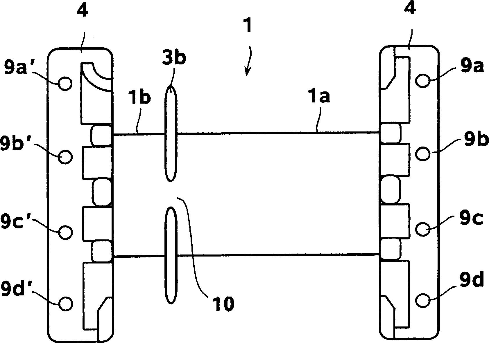
[0044] Figure 1 ~ Figure 3 Showing the high-voltage transformer of the first embodiment of the present invention, figure 1 Is an exploded perspective view of a high-voltage transformer, figure 2 Is a longitudinal section view of a high voltage transformer, image 3 It is a bottom view of the coil skeleton of a high-voltage transformer.
[0045] Such as figure 1 as well as figure 2 As shown, the high-voltage transformer of the first embodiment of the present invention is formed as follows: at both ends of the outer peripheral surface of the coil bobbin 1 having the transverse hollow portion 2 and near arbitrary ends (such as Figure 1 ~ Figure 3 In the example shown, close to the left end), flanges 3a, 3b, 3c are provided, terminal blocks 4 are provided on the left and right lower sides of the coil bobbin 1, and E-cores 5 are assembled from the left and right sides of the coil bobbin 1. .
[0046] The E-shaped core 5 is made of, for example, ferrite. The central leg 5a is ins...
no. 2 approach
[0056] Figure 4 ~ Figure 6 Showing the high-voltage transformer of the second embodiment of the present invention, Figure 4 Is an exploded perspective view of a high-voltage transformer, Figure 5 Is a longitudinal section view of a high voltage transformer, Figure 6 It is a bottom view of the coil skeleton of a high-voltage transformer.
[0057] Such as Figure 4 as well as Figure 5 As shown, the high-voltage transformer of the second embodiment of the present invention is formed as follows: flanges 23a and 23d are provided at both ends of the outer peripheral surface of a coil bobbin 21 having a transverse hollow portion 22, and a left and right transformer is provided in the center. The pair of flanges 23b and 23c are provided with terminal blocks 24 on the left and right sides of the lower part of the coil bobbin 21, respectively, and E-shaped cores 25 are assembled from the left and right sides of the bobbin 21, respectively.
[0058] The E-core 25 is constituted by subst...
Embodiment approach
[0067] The high-voltage transformer of the present invention is particularly preferably used in a high-pressure discharge lamp circuit, but if it is necessary to change the coupling coefficient of the primary winding and the secondary winding to adjust the leakage inductance, it can also be applied to various other transformers.
[0068] Also, the core used in the high-voltage transformer is preferably formed of ferrite, but in addition to this, for example, permalloy, sendust, carbonyl iron and other materials can also be used. Iron powder core obtained by compression molding of fine powder.
[0069] In addition, in each embodiment, two E-shaped cores are joined to form a core, but an I-shaped core and a U-shaped core may be combined to form a core.
[0070] In addition, the number of divisions of the primary winding is not limited to two, it may be three or more, and it may not be divided. In addition, the number of windings of the primary winding, the secondary winding, and the...
PUM
 Abstract
Description
Claims
Application Information
 - R&D
- Intellectual Property
- Life Sciences
- Materials
- Tech Scout
- Unparalleled Data Quality
- Higher Quality Content
- 60% Fewer Hallucinations
Browse by: Latest US Patents, China's latest patents, Technical Efficacy Thesaurus, Application Domain, Technology Topic, Popular Technical Reports.
© 2025 PatSnap. All rights reserved.Legal|Privacy policy|Modern Slavery Act Transparency Statement|Sitemap|About US| Contact US: help@patsnap.com