Torque limiter

A technology of torque limiter and rotation, which is applied in the direction of object separation, pile separation, thin material processing, etc., and can solve the problem of large-scale outer wheel body

Inactive Publication Date: 2008-10-29
SANCALL
View PDF1 Cites 8 Cited by
  • Summary
  • Abstract
  • Description
  • Claims
  • Application Information

AI Technical Summary

Problems solved by technology

[0012] For example, if the wall thickness of the peripheral wall of the above-mentioned outer ring body is increased, the strength of the above-mentioned gap can be improved, but at this time, the size of the outer ring body in the radial direction will be increased.

Method used


Image

  • Torque limiter
  • Torque limiter
  • Torque limiter

Examples


Embodiment Construction

[0040] Preferred embodiments of the torque limiter of the present invention will be described below with reference to the drawings.

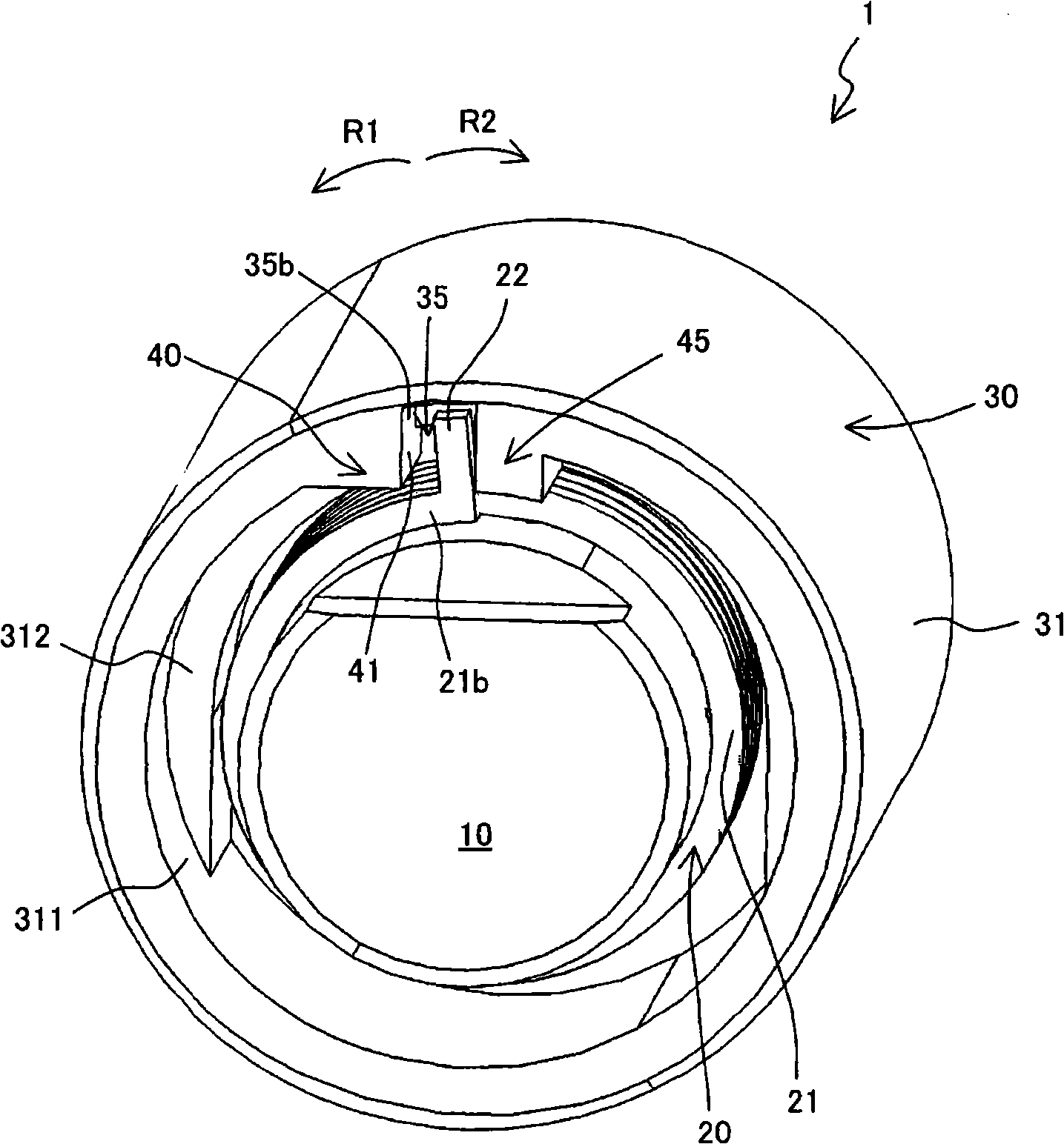
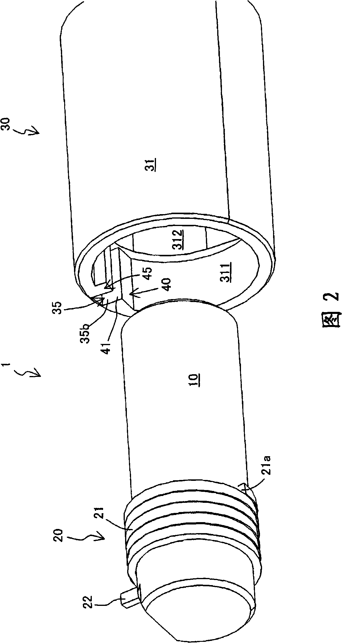
[0041] figure 1 2 and 2 respectively show a perspective view and an exploded perspective view of the torque limiter 1 of this embodiment.

[0042] like figure 1 As shown in FIG. 2, the above-mentioned torque limiter 1 has an inner ring body 10, a coil spring 20 wound on the above-mentioned inner ring body 10, and an inner ring body in a state where the above-mentioned coil spring 20 is wound is inserted. The hollow outer wheel body 30 of 10.

[0043] As shown in FIG. 2, the above-mentioned coil spring 20 has a winding portion 21 wound on the outer peripheral surface of the inner ring body 10, and a winding end portion 21b from the above-mentioned winding portion 21 (refer to figure 1 ) The hook portion 22 extending radially outward with the axis of the inner ring body 10 as a reference.

[0044]On the inner peripheral surface of the peripher...


PUM


Abstract

The invention provides a torque limiter, capable of preventing upsizing towards the radial direction and ensuring an enough intensity relative to so-called counter torque. A gap and a convex portion at locking side are mounted on an outer wheel body. The gap is blocked into a hook portion with coil springs, having a butt surface at opening side and a butt surface at locking side which are respectively butted with the hook portion when acting on the rotation torque facing to the opening side and the locking side. The convex portion at locking side includes an extension surface at locking side which extends towards inner side in the radial direction from the butt surface at locking side, and butts with the hook portion together with the butt surface at locking side when acting on the rotation torque facing to the locking side.

Description

technical field [0001] The present invention relates to a torque limiter applied to, for example, a separation roller of a sheet feeding device. Background technique [0002] A torque limiter that does not rotate even when an external force below a predetermined threshold is applied and rotates only when an external force exceeding the above threshold is applied is widely used as a separation roller of a sheet feeding device that feeds sheets one by one. . [0003] Specifically, the torque limiter includes an inner ring body, a coil spring wound around the inner ring body, and a hollow outer ring body inserted into the inner ring body wound with the coil spring. The coil spring has a winding portion wound around the outer peripheral surface of the inner ring, and a hook portion extending radially outward from a winding end portion of the winding portion with respect to the axis of the inner ring body. A slit into which the hook is engaged is provided on the peripheral wall...

Claims


Application Information

Patent Timeline
Patent Type & Authority Applications(China)
IPC IPC(8): B65H3/52B65H3/06
Inventor 蒲田真一外园佳孝冈本宪
Owner SANCALL
Why Eureka
Try Eureka