Apparatus for carrying out plasma chemical vapour deposition and method of manufacturing an optical precast product

一种化学气相沉积、等离子体的技术,应用在谐振腔的谐振器领域,能够解决衬底管有害、高纤维衰减、不稳定等问题

Active Publication Date: 2008-11-05
DRAKA COMTEQ BV
View PDF5 Cites 10 Cited by
  • Summary
  • Abstract
  • Description
  • Claims
  • Application Information

AI Technical Summary

Problems solved by technology

Such metal particles are not only harmful to the substrate tube, but also have a negative effect on the operation of the resonator, whereby the plasma chemical vapor deposition process becomes unstable
Furthermore, the presence of small metal particles in optical fibers leads to undesirably high fiber attenuation at certain wavelengths

Method used


Image

  • Apparatus for carrying out plasma chemical vapour deposition and method of manufacturing an optical precast product
  • Apparatus for carrying out plasma chemical vapour deposition and method of manufacturing an optical precast product

Examples


Embodiment Construction

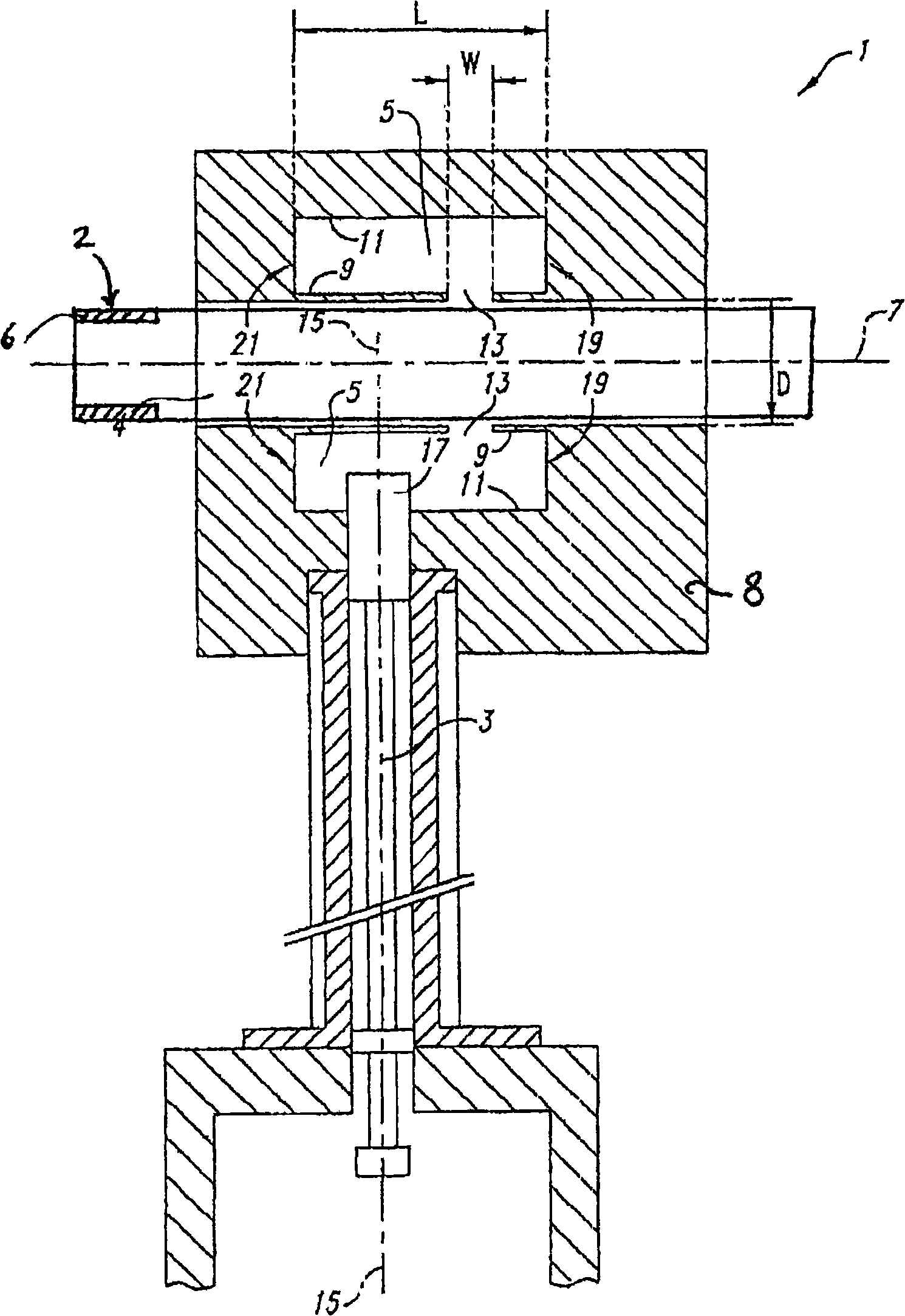
[0029] figure 1 is a cross-sectional view of a part of a PCVD apparatus 1 according to the invention. The device 1 comprises an elongated microwave guide 3 connected to a klystron (not shown) on a resonant cavity 5 extending circularly symmetrically around a cylindrical axis 7 . During deposition, the resonant cavity 5 moves back and forth along the cylindrical axis 7 so that the plasma region moves continuously along the length of the substrate tube (not shown). The resonance cavity 5 is substantially annular with a cylindrical inner wall 9 and a cylindrical outer wall 11 . The cylindrical inner wall 9 comprises a slit 13 which (in this embodiment) extends over the entire circumference around the cylinder axis 7 (in a plane perpendicular to the plane of the drawing). The microwave guide 3 has a (central) longitudinal axis 15 which extends substantially perpendicularly to the cylinder axis 7 . The longitudinal axis 15 and the slit 13 are offset relative to each other in suc...


PUM

PropertyMeasurementUnit
melting pointaaaaaaaaaa

Abstract

The present invention relates to an apparatus for carrying out plasma chemical vapour deposition, by which one or more layers of doped or undoped silica are deposited onto the interior of an elongated hollow glass substrate tube. The present Invention further relates to a method of manufacturing an optical preform by means of plasma chemical vapour deposition, wherein doped or undoped glass-forming gases are passed through the Interior of an elongated glass substrate tube, whilst conditions such that deposition of glass layers takes place are created in the interior of the substrate tube.

Description

technical field [0001] The invention relates to a device for performing plasma chemical vapor deposition, by means of which one or more layers of doped or undoped silicon oxide are deposited inside an elongated hollow glass substrate tube, the device comprising a Resonator of a resonator cavity formed substantially cylindrically symmetrically around a cylinder axis along which a substrate tube is placed, wherein the resonator cavity is substantially annular with a cylindrical inner wall and a cylindrical outer wall, and wherein the cylindrical The inner wall includes a slit extending along at least a part of the circumference around the cylindrical axis, and the microwave guide extends into the resonant cavity, so that microwaves can exit through the aforementioned slit to the cavity enclosed by the cylindrical inner wall, wherein the resonator includes Around at least a portion of the substrate tube and movable back and forth along the longitudinal axis of the substrate tube....

Claims


Application Information

Patent Timeline
Patent Type & Authority Applications(China)
IPC IPC(8): C23C16/40C23C16/42C23C16/44
CPCC03B2201/12C03B2201/31C03B37/01823C03B37/0183
Inventor M·J·N·范斯特拉伦I·米利克维克J·A·哈特苏伊克
Owner DRAKA COMTEQ BV
Why Eureka
Try Eureka