Connector and medical apparatus

A technology for medical devices and connectors, which is applied to two-part connecting devices, parts and components of connecting devices, and connections, can solve problems such as poor electrical connection, inability to use connectors, and reduced light intensity, and achieve the effect of improving reliability.

Inactive Publication Date: 2013-06-12
OLYMPUS CORP
View PDF7 Cites 0 Cited by
  • Summary
  • Abstract
  • Description
  • Claims
  • Application Information

AI Technical Summary

Problems solved by technology

[0015] However, the connectors disclosed in Patent Documents 1 to 5 are composed of a male-side connector and a female-side connector that are fitted together so that electrical and optical connections can be performed at the same time, but the insertion of the male-side connector and the female-side connector Accuracy is required
In other words, repeated attachment and detachment of the male-side connector and the female-side connector may result in poor electrical connection if abrasion occurs between the two.
In addition, in the optical connection part, even a slight deviation of the axis center will cause a decrease in the amount of light. Especially in the connection of the optical fiber for illumination of the endoscope device, since high light transmission efficiency is required, the patent cannot be adopted. Connectors disclosed in Documents 1 to 5
[0016] Furthermore, even in the connection of the peripheral equipment of the medical device disclosed in Patent Documents 6 and 7 and the insertion part side main body of the endoscope electrically connected to it, repeated attachment and detachment, if there is wear and tear between the two, there will be May cause poor electrical connection

Method used


Image

  • Connector and medical apparatus
  • Connector and medical apparatus
  • Connector and medical apparatus

Examples


Embodiment Construction

[0047] Embodiments of the present invention will be described below with reference to the drawings.

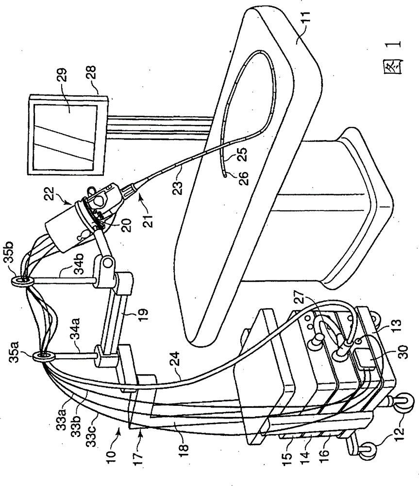
[0048] Figure 1 to Figure 8shows the first embodiment. figure 1 It shows the overall structure of the medical device 10 and is a perspective view of a state in which the medical device 10 is installed beside the operating table 11 . A light source device 14 , a video processor 15 , a control box 16 , and the like are mounted on a support stand 13 provided with casters 12 . A pillar 18 constituting a support mechanism 17 is erected vertically on the support table 13, and an endoscope holding portion as a medical device holding portion is provided on the upper end of the pillar 18 via an arm 19 rotatable in a horizontal plane. 20.

[0049] An endoscope 21 as a medical instrument is held on the endoscope holding unit 20 . The endoscope 21 is composed of a main body 22 , an insertion portion 23 connected to the main body 22 , and a universal cord 24 . The insertion portion 2...


PUM


Abstract

A connector includes a flange receiving portion (89) serving as a first standard surface provided on a chassis (85) serving as a stationary base plate, a casing (93) serving as a first connector portion which is supported in a manner to be movable at least in parallel to the flange receiving portion (89), a flange receiving portion (105) serving as a standard surface which is provided on the casing (93) and is substantially parallel to the flange receiving portion (89), and a light guide fixing member (109) serving as a second connector portion which is supported in a manner to be movable at least in parallel to the flange receiving portion (105).

Description

technical field [0001] The present invention relates to a connector and a medical device used in a medical device including, for example, an endoscope main body located on the proximal end side of an operating part of the endoscope and a power unit connected to the endoscope main body. Background technique [0002] As a connector for connecting electricity, fluid, light, etc., such a multifunctional connector is known: it is composed of a male-side connector and a female-side connector that are fitted together, and the inner peripheral surface of the female-side connector is provided with a There is an electrical connection portion, and an optical connection portion is provided at the axial center of the female connector, and the male connector is inserted into the female connector to simultaneously perform electrical and optical connections (for example, refer to Patent Documents 1 and 2). [0003] In addition, as a connector for electrical signals and optical signals, ther...

Claims


Application Information

Patent Timeline
Patent Type & Authority Patents(China)
IPC IPC(8): A61B1/00H01R13/631H01R24/58
CPCA61B1/00126G02B6/3817G02B6/3853A61B1/00124H01R13/6315A61B1/00128G02B6/3833
Inventor 宫城正明泽井贵司
Owner OLYMPUS CORP
Why Eureka
Try Eureka