This helps you quickly interpret patents by identifying the three key elements:
Problems solved by technology
Method used
Benefits of technology
Benefits of technology
The patent describes an antenna device for vehicles that includes a metal plate to adjust the resonance frequency of unnecessary resonance and a resin base to secure the fixing strength to the roof. The metal plate can be easily installed and has the ability to be adjusted for different vehicles and mounting positions. This results in a smaller antenna device that can be securely installed on different roof shapes, ensuring stable performance regardless of the vehicle's specification. Additionally, the resin base prevents position shifts of the metal plate, making attachment work easier. The technical effects include improved antenna gain and a small-sized antenna device for vehicles that can be easily installed in various mounting positions.
Problems solved by technology
However, the shape of the roof as a portion to which an antenna device for vehicle is mounted is not flat.
In this case, corrosion may occur to the conductor plate.
Thus, changes in design, of course, and maintaining multiple kinds take manufacturing cost and management cost compared to a case of maintaining few kinds.
However, this may not be considered as a really preferable solution in terms of costs for the antenna device for vehicle, size reduction of the antenna device for vehicle, appearance of the antenna device for vehicle when mounted on the vehicle, and so forth.
Method used
Image
Click on the blue label to locate the original text in one second.
Reading with bidirectional positioning of images and text.
Examples
first embodiment
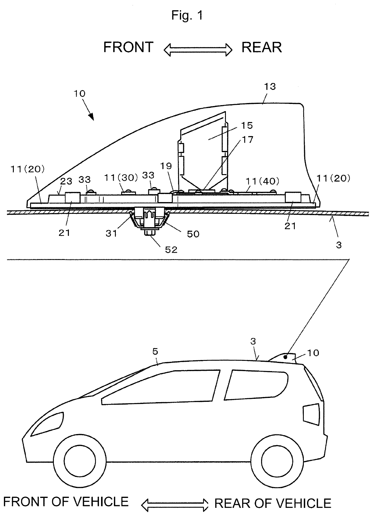
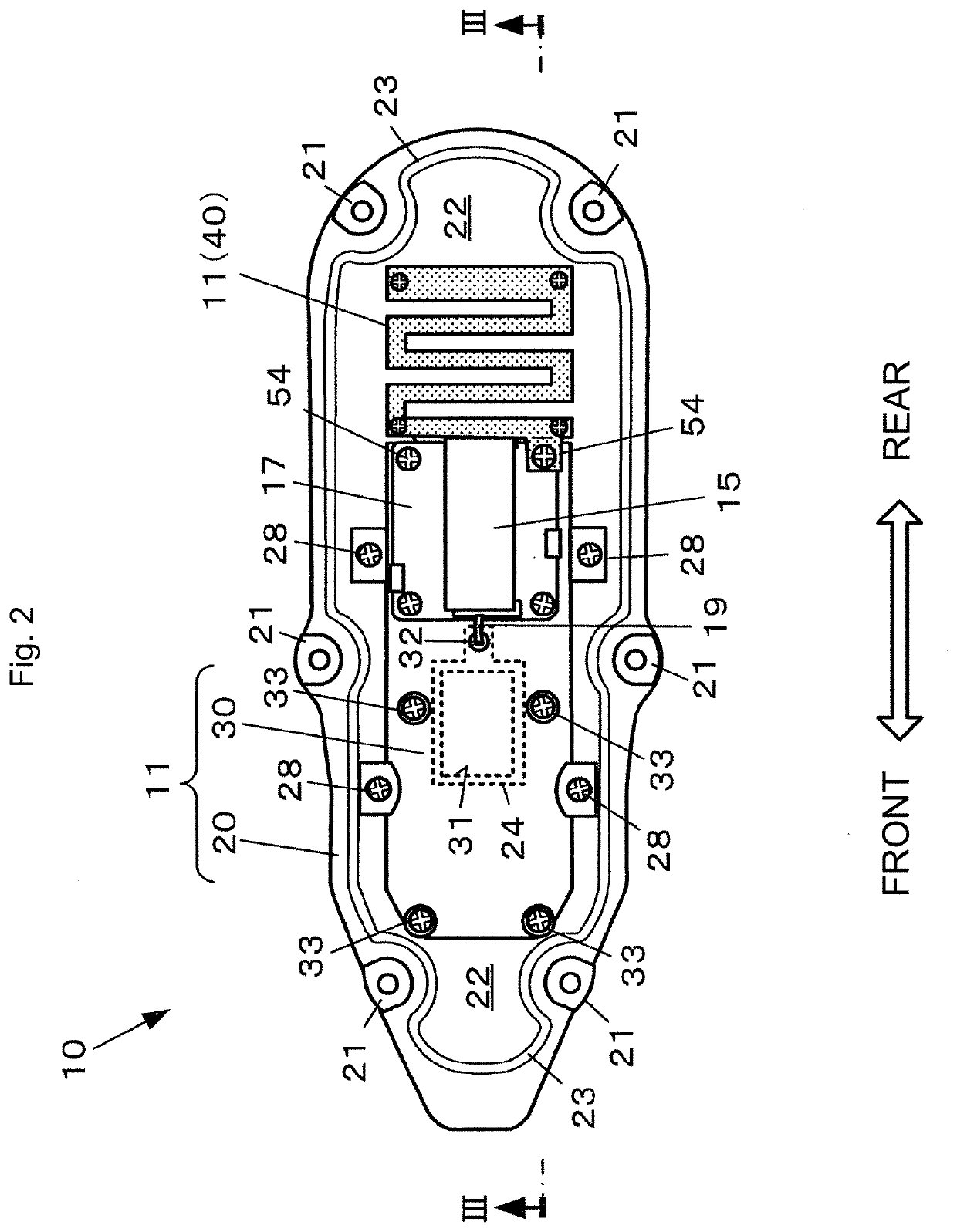
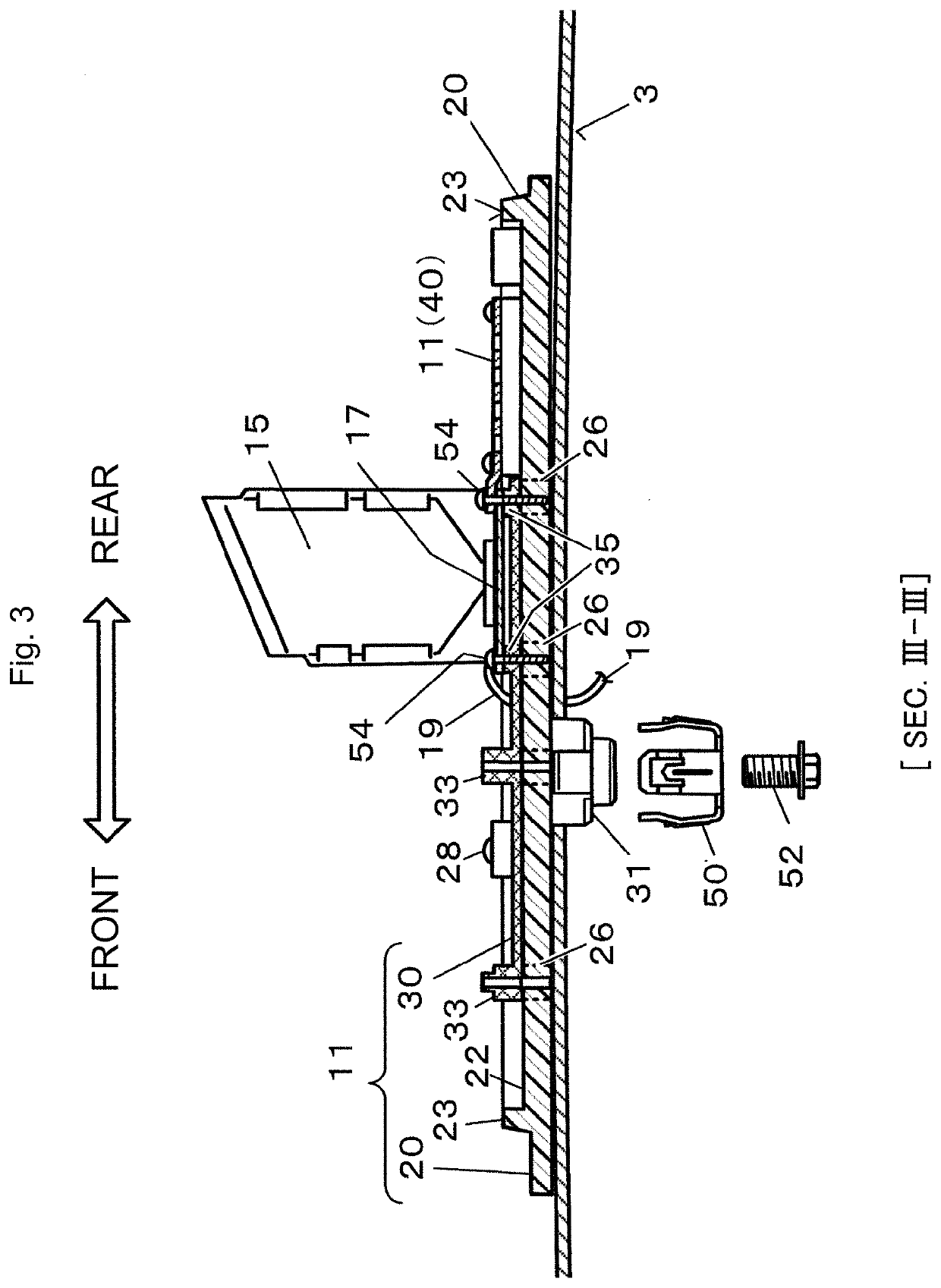
[0059]FIG. 1 is a side perspective view that illustrates a configuration example of an antenna device 10 of this embodiment. FIG. 2 is a plan view of a state where an antenna case 13 of the antenna device 10 of this embodiment is detached, that is, an internal plan view. FIG. 3 is a cross-sectional view taken along line III-III in FIG. 2.
[0060]As illustrated in FIG. 1, the antenna device 10 is an antenna device designed on the assumption that it is mounted on an exterior structure that corresponds to a roof 3 of a vehicle 5 (such as a passenger vehicle, a truck, or an agricultural machine, for example) and is an antenna device that incorporates an antenna element and so forth in a case. “Front and rear” in the antenna device 10 denote the same directions as front and rear of the vehicle 5 in which the antenna device 10 is mounted on the roof 3 and mean the directions illustrated in FIG. 1. That is, those are the front-rear direction along a streamlined external appearance, the side ...
second embodiment
[0090]Next, a second embodiment to which the present invention is applied will be described.
[0091]In the first embodiment, the method that lowers the resonance frequency of the unnecessary resonance, is employed. However, in this embodiment, a method that conversely raises the resonance frequency of the unnecessary resonance, is employed. In the following, a description will mainly be made about differences from the first embodiment, the same reference numerals are provided to similar configuration elements to the first embodiment, and duplicated descriptions thereof will be omitted.
[0092]FIG. 6 is a plan view of a state where an antenna case of an antenna device 10B of this embodiment is detached. In an antenna base 11B of the antenna device 10B, a metal base 30B is made shorter in the longitudinal direction (front-rear direction) than the antenna base 11 of the first embodiment. Specifically, a metal plate 40B is provided with a gap which is provided on a front end side of the met...
modification examples
[0097]In the above, the examples of the embodiments to which the present invention is applied are described. However, forms to which the present invention is applicable are not limited to the above forms, but appropriate addition, omission, and alterations of the configuration elements may be conducted.
PUM
Abstract
An antenna device for vehicle that is attached to a roof of a vehicle, the antenna device for vehicle including: an antenna base; an antenna case covering the antenna base from above; and an antenna element provided inside the antenna case, wherein the antenna base has a metal base fixed to the roof, and a metal plate electrically connected to the metal base.
Description
TECHNICAL FIELD[0001]The present invention relates to an antenna device for vehicle that is attached to a roof of a vehicle.BACKGROUND ART[0002]An antenna device for vehicle that is attached to a roof of a vehicle such as an automobile has been known, the antenna device for vehicle accommodating an antenna element in a streamlined case in consideration of fluid resistance. In general, the antenna device for vehicle is mounted on a center in a rear portion of the roof and may be referred to as “shark fin antenna”, “dolphin antenna”, or the like because of the figure of the vehicle with the antenna device for vehicle mounted and the appearance of the antenna device for vehicle.[0003]For example, Patent Literature 1 specifically discloses an antenna device for vehicle in which an antenna case is put on a resin base and a space for accommodating a metal base functioning as a ground plate, an antenna element, and so forth is thereby defined. Patent Literature 1 describes a structure whic...
Claims
Application Information
Patent Timeline
Application Date:The date an application was filed.
Publication Date:The date a patent or application was officially published.
First Publication Date:The earliest publication date of a patent with the same application number.
Issue Date:Publication date of the patent grant document.
PCT Entry Date:The Entry date of PCT National Phase.
Estimated Expiry Date:The statutory expiry date of a patent right according to the Patent Law, and it is the longest term of protection that the patent right can achieve without the termination of the patent right due to other reasons(Term extension factor has been taken into account ).
Invalid Date:Actual expiry date is based on effective date or publication date of legal transaction data of invalid patent.

