Piezo inkjet printer

Inactive Publication Date: 2006-09-21
OCE TECH
View PDF9 Cites 0 Cited by
  • Summary
  • Abstract
  • Description
  • Claims
  • Application Information

AI Technical Summary

Benefits of technology

[0007] According to one embodiment where the transducer comprises polarized piezo-electric material, the polarization direction of the first part is essentially opposed to the polarization direction of the second part. According to this embodiment, a deformation of both parts in opposing directions is very easily arranged. By arranging an opposing polarization direction for both parts, actuation of the transducer will automatically deform the first part in a direction opposite to the second part. An additional advantage of this embodiment is that for a common type of piezo-electric transducer, i.e., the type where various layers of piezo-electric material are separated from each other by electrodes, the largest part of the process of producing a transducer of this kind (consolidating the layer assembly, sintering the layers, cutting the individual piezo transducers, etc.) is identical to producing the known transducers.
[0008] According to an alternative embodiment where the transducer is made up of a number of layers of piezo-electric material which are separated from each other by electrodes, the electrodes in the first part are polarized differently compared to the electrodes in the second part. According to this embodiment, the first part is also actuated with one and the same actuati

Problems solved by technology

If the pressure wave is strong enough, this leads to a drop of ink being ejected from the duct nozzle.
In this manner, each individual actuation may lead to a drop of ink being ejected.
However, the known printer does have major disadvantages.
High voltages reduce the lifespan of the transducer and therefore that of the printhead.
Furthermore, it will be virtually impossible for fourth or higher order vibrations to obtain large enough volume changes using one transducer.
The disadvanta

Method used


Image

  • Piezo inkjet printer
  • Piezo inkjet printer
  • Piezo inkjet printer

Examples


Example

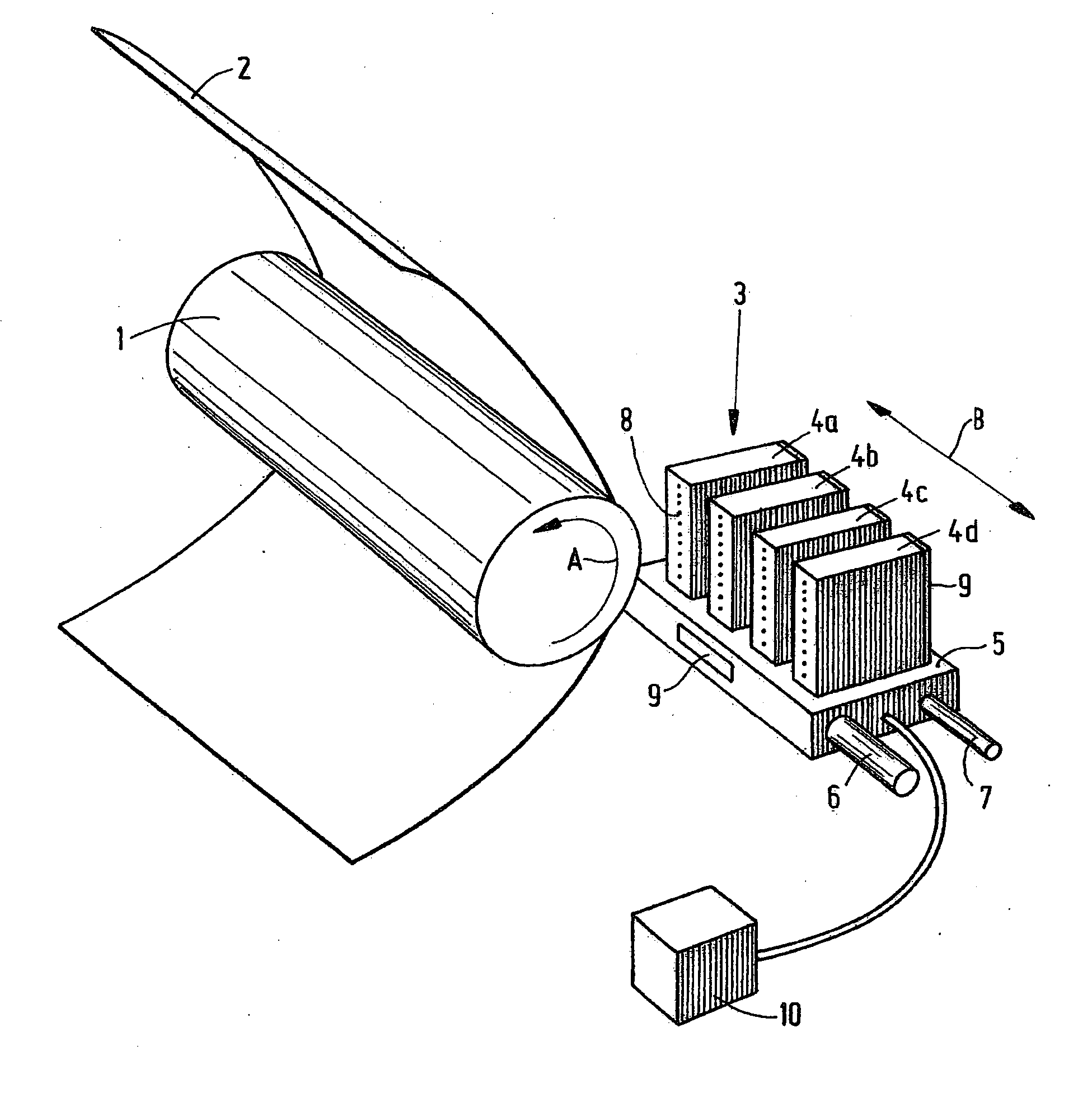
[0016]FIG. 1 is a diagram showing an inkjet printer. According to this embodiment, the printer comprises a roller 1 used to support a receiving medium 2, such as a sheet of paper or a transparency, and move it across a carriage 3. The carriage comprises a carrier 5 to which four printheads 4a, 4b, 4c and 4d have been fitted. Each printhead contains its own color, in this case cyan (C), magenta (M), yellow (Y) and black (K), respectively. The printheads are heated using heating elements 9, which have been fitted to the rear of each printhead 4 and to the carrier 5. The temperature of the printheads is maintained at the correct level by the application of a central control unit 10 (controller).

[0017] The roller 1 rotates around its own axis as indicated by arrow A. In this manner, the receiving medium may be moved in the sub-scanning direction (often referred to as the X direction) relative to the carrier 5, and therefore also relative to the printheads 4. The carriage 3 may be moved...


PUM


Abstract

An inkjet printer containing a substantially closed ink duct and a transducer used to generate a pressure wave in the duct, wherein the transducer comprises a first part and, separate from the first part, a second part whereby, by actuation of the transducer, the first part manifests a first deformation and the second part simultaneously manifests a second deformation actually opposed to the first deformation, such that a pressure wave is generated in the ink duct.

Description

[0001] This application claims priority to Dutch Patent Application No. 1028546 filed on Mar. 15, 2005 in The Netherlands, the entire contents of which is hereby incorporated by reference in its entirety. BACKGROUND OF THE INVENTION [0002] The present invention relates to an inkjet printer containing a substantially closed ink duct and a transducer that is substantially parallel to the closed duct, this transducer deforming by actuation in order to generate a pressure wave in the duct. [0003] An inkjet printer of this kind is known from U.S. Pat. No. 4,688,048. As is known from the prior art, actuation of a transducer of the above kind causes it to deform, so that a sudden volume change occurs in the duct (also referred to as “ink chamber”). This produces a pressure wave in the duct. If the pressure wave is strong enough, this leads to a drop of ink being ejected from the duct nozzle. In this manner, each individual actuation may lead to a drop of ink being ejected. By imposing such...

Claims


Application Information

Patent Timeline
IPC IPC(8): G01L11/00
CPCB41J2/14274
Inventor WIJSHOFF, HERMANUS M. A.
Owner OCE TECH
Why Eureka
Try Eureka