Electric cleaner

A vacuum cleaner and electric technology, which is applied in the direction of vacuum cleaners, suction filters, cleaning filter devices, etc., can solve the problems of low suction power, insufficient centrifugal separation of dust, and enlarged curved suction path, etc., to achieve high suction power, Excellent air volume maintenance performance and the effect of ensuring air permeability

Inactive Publication Date: 2008-11-19
PANASONIC CORP
View PDF1 Cites 7 Cited by
  • Summary
  • Abstract
  • Description
  • Claims
  • Application Information

AI Technical Summary

Problems solved by technology

[0003] But, in above-mentioned existing structure, although produce cyclone airflow in dust box, utilize the airflow after the suction and separate dust with centrifugal force, thereby dust is piled up in dust box, but most are due to being guaranteed higher suction power limitations, and become a mechanism that cannot sufficiently centrifuge dust
Therefore, if dust is accumulated in the dust box, the accumulated dust itself acts as a filter, so fine dust is still attached to the accumulation of coarse dust, which constitutes ventilation resistance, and there is a problem that the suction force drops rapidly.
In addition, in order to generate whirlwind airflow, it is necessary to increase the curved suction path, and because swirling airflow also occurs during suction, the pressure loss in the path from suction to exhaust in the dust box increases, and the suction power becomes lower. The problem

Method used


Image

  • Electric cleaner
  • Electric cleaner
  • Electric cleaner

Examples


Embodiment approach 1

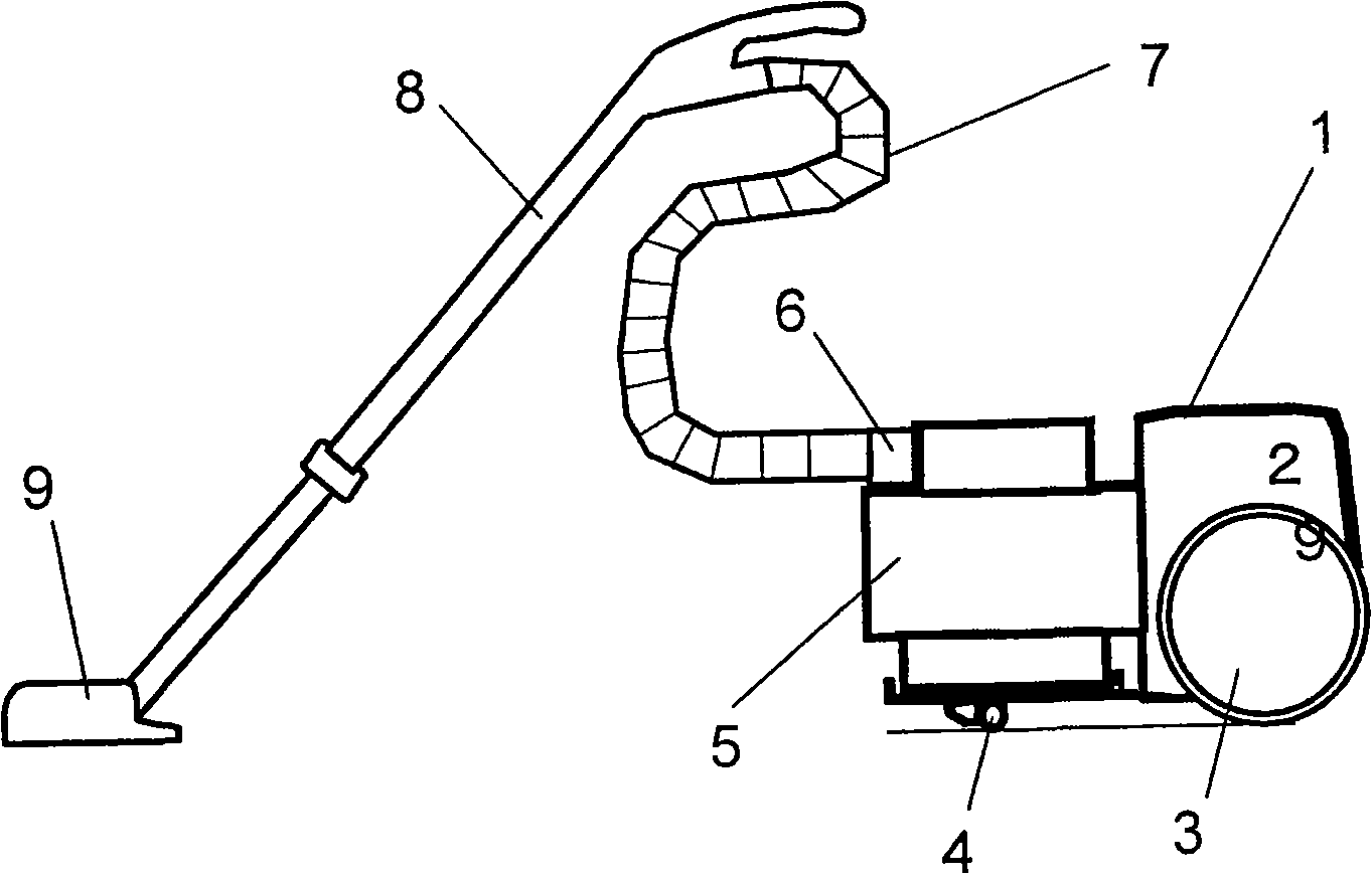
[0147] 1 and 2 show an electric vacuum cleaner according to Embodiment 1 of the present invention.

[0148] As shown in FIG. 2 , the electric vacuum cleaner main body 1 is equipped with an electric blower 21 that generates suction airflow. In addition, wheels 3 and casters 4 are installed outside the electric vacuum cleaner main body 1 to move freely on the ground. Furthermore, on the upstream side of the electric blower 21, there is provided a dust collecting box 5 that can be freely attached to and detached from the main body 1 of the electric vacuum cleaner through a partition wall 26 having air permeability. Dusty air.

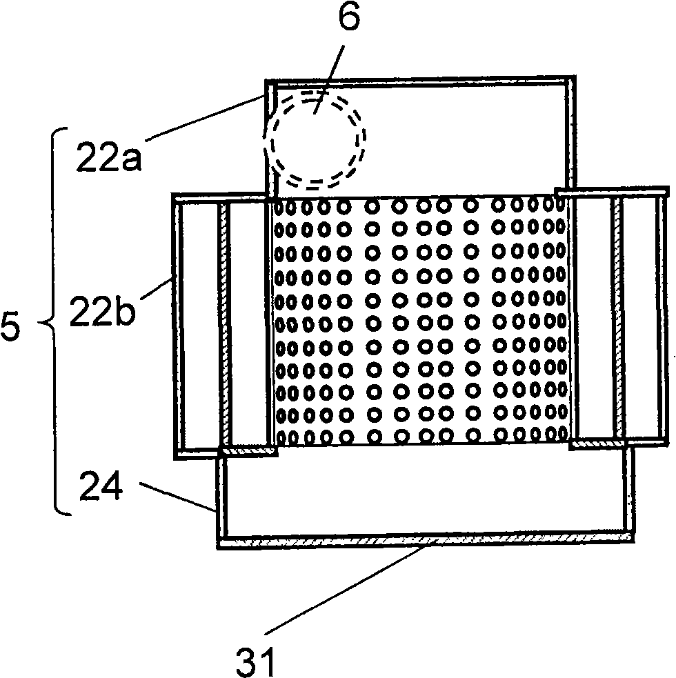
[0149] In addition, the dust collecting box 5 is composed of a plurality of hollow cylinders with different diameters connected into a multi-stage shape. In the first embodiment, it is a three-stage structure, and includes the box upper part 22a, the box central part 22b, and the dust collector in order from the upper stage. Storage section 24. The case ...

Embodiment approach 2

[0188] Next, Embodiment 2 of the present invention will be described. Hereinafter, differences in configuration and operation from Embodiment 1 will be mainly described, and elements that are the same as those in Embodiment 1 will be assigned the same reference numerals, and descriptions of the configuration and operation will be omitted.

[0189] 10 , 11A, 11B, 11C, and 11D are cross-sectional views showing the electric vacuum cleaner and dust collecting box 5 according to Embodiment 2. FIG.

[0190] As shown in Figures 10, 11A, 11B, 11C, and 11D, the difference from Embodiment 1 is that not only a cylindrical dust filter 27 is provided in the dust collecting box 5, but also a hollow disc-shaped third The dust removal filter 28 , the third dust removal filter 28 is provided below the cylindrical dust removal filter 27 .

[0191] This 3rd dust removal filter 28 is made of coarse dust filter, and the same as the first dust removal filter 21, is the metal screen cloth of 250 mi...

Embodiment approach 3

[0210] Next, Embodiment 3 of the present invention will be described. Hereinafter, differences in configuration and operation from Embodiments 1 and 2 will be mainly described, and the same elements will be assigned the same reference numerals, and descriptions of the configuration and operation will be omitted.

[0211] FIG. 14 is a cross-sectional view of a part of cylindrical dust filter 27 seen from above. About other structures, it is the same as Embodiment 2.

[0212] As shown in FIG. 14 , a drive gear 141 is provided on the sealing portion 43 of the upper outer periphery of the second dust filter 27 b constituting the cylindrical dust filter 27 , and the other drive gear 142 fitted with the drive gear 141 , and the rotating motor 143 that drives the drive gear 142 to rotate, the second dust removal filter 27b and the first dust removal filter 27b rotate integrally.

[0213] Again, in this way, both the first dust removal filter 27a and the second dust removal filter 2...


PUM


Abstract

The invention provides an electric cleaner, which is hardly reduced in its suction even after it sucked dust, while retaining a high sucking work per unit time. Therefore, a dust collecting case for introducing the air containing the dust, which has been sucked by an electric blower, has a cylindrical shape, including a suction port for introducing the air containing the dust in the tangential direction and a dust storing portion on the other end side of the suction port. A dust eliminating filter in the dust collecting case is arranged in a wind passage, with which the dust collecting case and the electric blower communicate. By a swirling air flow in the dust collecting case, therefore, the dust is continuously swirled in the dust collecting case. As a result, the dust is separated, even in case it sticks to the dust eliminating filter, from the face of the dust eliminating filter, thereby to retain an intake air passage at all times.

Description

technical field [0001] The present invention relates to an electric vacuum cleaner using a reusable dust box. Background technique [0002] All the time, as this electric vacuum cleaner, known following structure: promptly produce special-purpose cyclone airflow in dust box, utilize the airflow after the suction and separate dust with centrifugal force, thereby dust is accumulated in dust box (for example, refer to patent Document 1: Japanese Patent Application Laid-Open No. 2000-342492). [0003] But, in above-mentioned existing structure, although produce cyclone air-flow in dust box, utilize the air-flow after the suction and separate dust with centrifugal force, thereby dust is piled up in dust box, but most are due to being guaranteed higher suction power However, it becomes a mechanism that cannot sufficiently centrifuge dust. Therefore, if dust is accumulated in the dust box, the accumulated dust itself acts as a filter, so fine dust is also attached to the accumula...

Claims


Application Information

Patent Timeline
Patent Type & Authority Applications(China)
IPC IPC(8): A47L9/16A47L9/12A47L9/10
CPCA47L9/1683A47L9/1666A47L9/1675A47L9/127A47L9/20A47L9/1608A47L9/26A47L9/16A47L9/10
Inventor 中野幸一甲田哲也广田正宣村上诚福本正美
Owner PANASONIC CORP
Why Eureka
Try Eureka