Delayed action spring force element for nasal dilators

A nasal dilator and spring force technology, applied in the field of spring force components used for delayed action of nasal dilators, can solve the problems of nasal dilator detachment, insufficient viscosity to offset the spring force of external nasal dilators, etc.

Inactive Publication Date: 2008-11-26
CNS INC
View PDF0 Cites 3 Cited by
  • Summary
  • Abstract
  • Description
  • Claims
  • Application Information

AI Technical Summary

Problems solved by technology

As mentioned above, the problem with hydrocolloid adhesives is that they are initially not viscous enough to counteract the spring force of the external nasal dilator, which can cause the nasal dilator to detach from the skin

Method used


Image

  • Delayed action spring force element for nasal dilators
  • Delayed action spring force element for nasal dilators
  • Delayed action spring force element for nasal dilators

Examples


Embodiment Construction

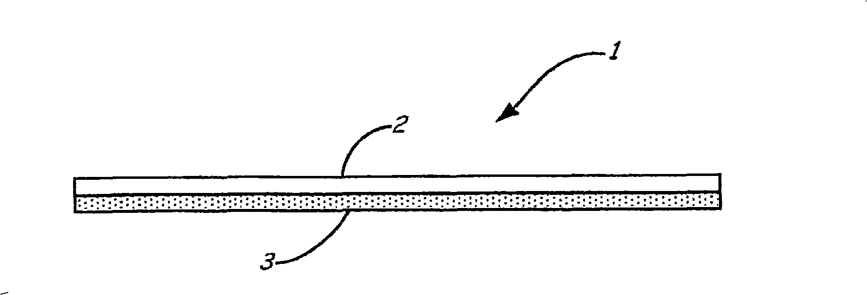
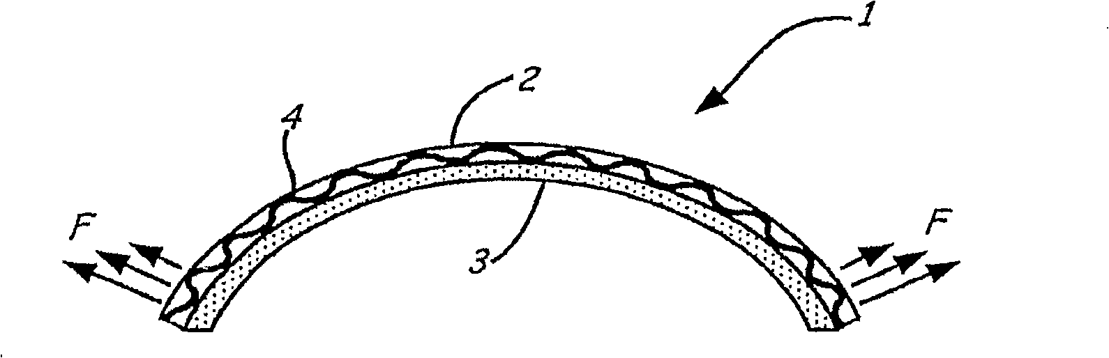
[0017] The present invention comprises two parts forming a nasal dilator strip 1 as shown in FIG. 1 . The spring force layer 2 has a minimum spring force in its latent state, usually a flat state as shown in FIG. 1 . The skin contact layer 3 provides a substrate for adhesion to the nose and is likely to be a hydrocolloid or similar material. As shown in Figure 3, an optional fiber or wire mesh frame 4 can be incorporated into the spring force layer 2 to provide a grid that can shrink and stiffen.

[0018] While the embodiments described herein describe components in layered form, other configurations, such as embedded components, are also within the scope of the invention.

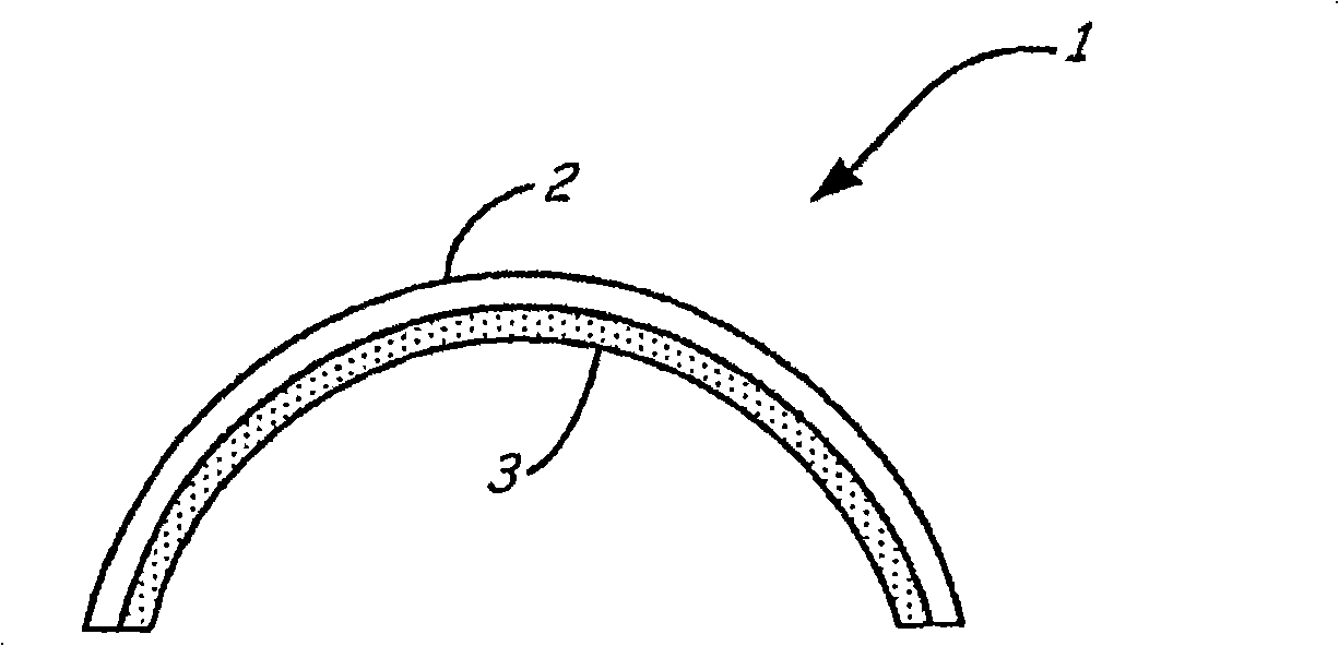
[0019] The nasal dilator strip 1 is attached to the nose by bending the strip 1 to conform to the outer surface of the nose, as shown in FIG. 2 . When a certain activation process is performed, the spring force layer 2 contracts, thereby obtaining an outward spring force F sufficient to be used as a nasa...


PUM


Abstract

A nasal dilator, having a spring force that can be activated after the dilator is applied to the nose, is described. The nasal dilator has a spring force component and an adhesive component, which together act to dilate nasal tissues to help open or keep open the nasal valve to alleviate snoring and other breathing-related disorders.

Description

[0001] This application claims the benefit of the filing date and content of US Provisional Patent Application 60 / 734,676, filed November 7,2005. technical field [0002] External nasal dilators used to relieve snoring and other breathing related disorders are used to perform two opposing functions. First, the dilator needs to be firmly attached to the nasal skin. Second, the dilator applies an outward force to open the nasal valve area. If the initial adhesion is insufficient, a second outward force will cause the dilator to disengage. In current nasal dilators, adhesives such as acrylate adhesives are used to bond relatively quickly so that the outward spring force does not cause disengagement as would normally occur. Background technique [0003] However, the use of pressure sensitive acrylate adhesives is problematic. For example, in removing strong bonds from acrylate adhesives (better to skin when less tacky), which lose tack when sweated and which potentially clog ...

Claims


Application Information

Patent Timeline
Patent Type & Authority Applications(China)
IPC IPC(8): A61M29/00
CPCA61F5/56A61F5/08A61M29/00
Inventor 古斯塔夫·R·芬顿
Owner CNS INC
Why Eureka
Try Eureka