Automatic polarity regulating apparatus of charging circuit

An automatic adjustment device and charging circuit technology, which is applied in the direction of battery circuit devices, circuit devices, emergency protection circuit devices, etc., can solve the problems of unable to charge the battery, damage the charging circuit and the battery, etc., to avoid the failure to charge or damage the charging circuit and The effect of the battery

Inactive Publication Date: 2008-12-03
HONG FU JIN PRECISION IND (SHENZHEN) CO LTD +1
View PDF0 Cites 0 Cited by
  • Summary
  • Abstract
  • Description
  • Claims
  • Application Information

AI Technical Summary

Problems solved by technology

However, due to mistakes or other external factors, the reverse connection may still occur, resulting in failure to charge the battery, and may even damage the charging circuit and the battery.

Method used


Image

  • Automatic polarity regulating apparatus of charging circuit

Examples


Embodiment Construction

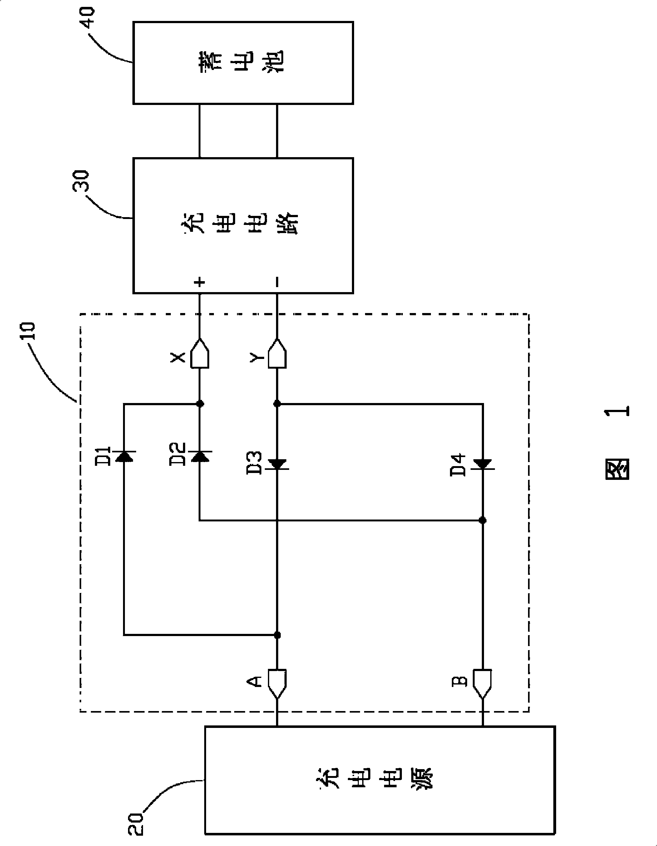
[0009] Please refer to Fig. 1, the preferred embodiment of the charging circuit polarity automatic adjustment device 10 of the present invention comprises a first diode D1, a second diode D2, a third diode D3, a fourth diode Tube D4; two input terminals A and B are used to connect the positive and negative output terminals of a charging power source 20 such as a solar power supply; and two output terminals X and Y are respectively connected to the positive and negative input terminals of a charging circuit 30. The charging power source 20 can charge a storage battery 40 through the charging circuit 30 .

[0010] The anode of the first diode D1 is connected to the input terminal A, and the cathode is connected to the output terminal X. The anode of the second diode D2 is connected to the input terminal B, and the cathode is connected to the output terminal X. The cathode of the third diode D3 is connected to the input terminal A, and the anode is connected to the output termin...


PUM


Abstract

The invention provides a charging circuit polarity automatic adjusting device, comprising a first diode, a second diode, a third diode, a fourth diode, a first input terminal, a second input terminal, a first output terminal and a second output terminal; the anode of the first diode is connected with the first input terminal and the cathode thereof is connected with the first output terminal; the anode of the second diode is connected with the second input terminal and the cathode thereof is connected with the first output terminal; the cathode of the third diode is connected with the first input terminal and the anode thereof is connected with the second output terminal; the cathode of the fourth diode is connected with the second input terminal and the anode thereof is connected with the second output terminal. The adjusting device can automatically adjust the polarity so as to lead the polarity of the charging power output terminal to match with the polarity of the charging circuit input terminal.

Description

technical field [0001] The invention relates to a device for adjusting the polarity of a charging circuit. Background technique [0002] At present, the two output terminals of the general charging power supply, such as solar charging power supply, have positive (+) and negative (-) polarities. When charging, connect the positive and negative output terminals to the positive and negative input terminals of the corresponding charging circuit respectively. After that, the battery connected to the charging circuit can be charged. [0003] Usually, there are signs indicating the positive and negative polarity at the positive and negative input terminals of the charging circuit to prevent the polarity of the charging power supply and the charging circuit from being reversed. However, due to mistakes or other external factors, the reverse connection may still occur, resulting in failure to charge the storage battery, and may even damage the charging circuit and the storage batter...

Claims


Application Information

Patent Timeline
Patent Type & Authority Applications(China)
IPC IPC(8): H02J7/00H02H7/18
CPCH02J7/0034
Inventor 谢明志
Owner HONG FU JIN PRECISION IND (SHENZHEN) CO LTD
Why Eureka
Try Eureka