Anti-swing mechanism of container gantry crane sling

A gantry crane and container technology, applied in the field of cranes, can solve the problems of inability to achieve anti-swing effect, difficult to form motion damping, difficult maintenance and use, etc., and achieve the effects of easy adjustment and consistency, improved operation efficiency, and simple structure

Inactive Publication Date: 2008-12-17
SANY MARINE HEAVY IND
View PDF1 Cites 33 Cited by
  • Summary
  • Abstract
  • Description
  • Claims
  • Application Information

AI Technical Summary

Problems solved by technology

However, due to the winding method of the steel wire rope, when the spreader 2 swings, there are only two triangles of motion damping in the movement direction of the cart and the movement direction of the trolley, so the best anti-sway effect cannot be achieved.
In particular, when the load is unbalanced, the spreader 2 will swing diagonally, that is, torsion and vibration will occur, and the above-mentioned anti-sway mechanism is difficult to form effective motion damping
[0007] In addition, the anti-sway mechanism includes two reels, twelve pulleys, and eight steel wire ropes. It has a large number of components, a relatively complicated structure, and difficult maintenance and use.
Moreover, due to the small gap between the box twist locks (generally about 8 mm), the length of the eight wire ropes must be adjusted frequently during use to ensure the level of the spreader 2, otherwise it will be difficult to align the box; however, each The expansion and contraction of steel wire ropes are different, and there are inevitably manufacturing errors and installation errors. In fact, it is difficult to adjust the lengths of the eight steel wire ropes under stress, which makes it difficult to align the boxes.

Method used


Image

  • Anti-swing mechanism of container gantry crane sling
  • Anti-swing mechanism of container gantry crane sling
  • Anti-swing mechanism of container gantry crane sling

Examples


Embodiment Construction

[0025] The present invention will be further described below in conjunction with the accompanying drawings and specific embodiments.

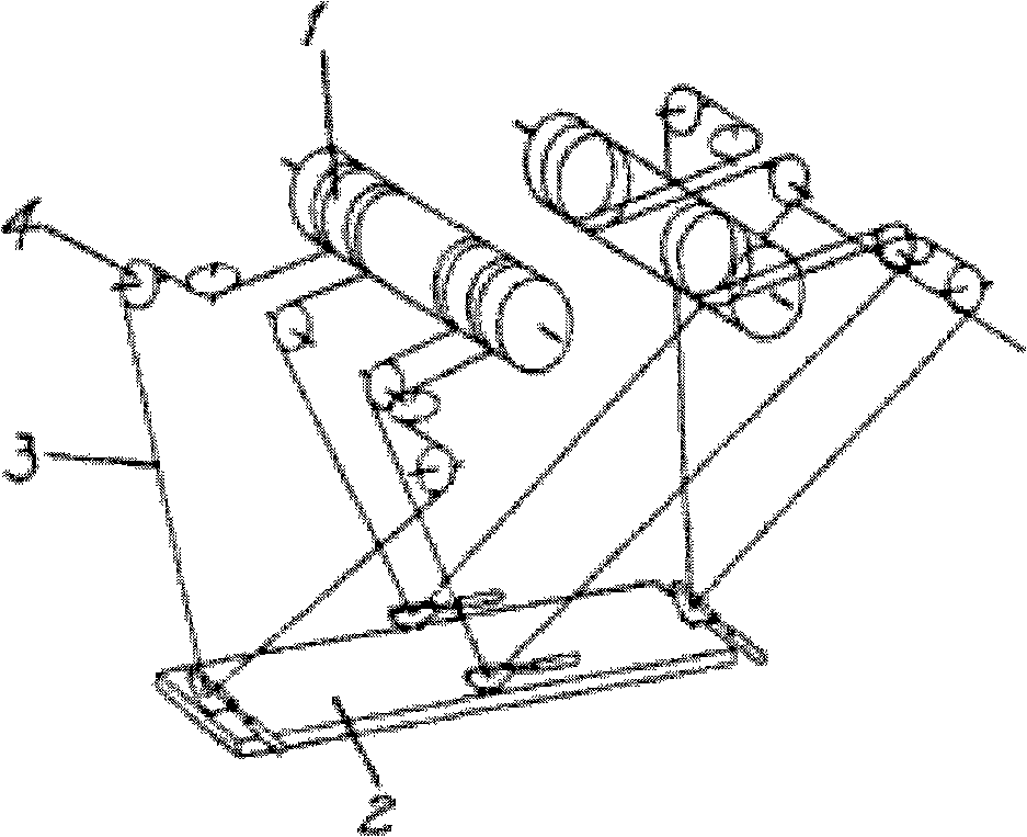
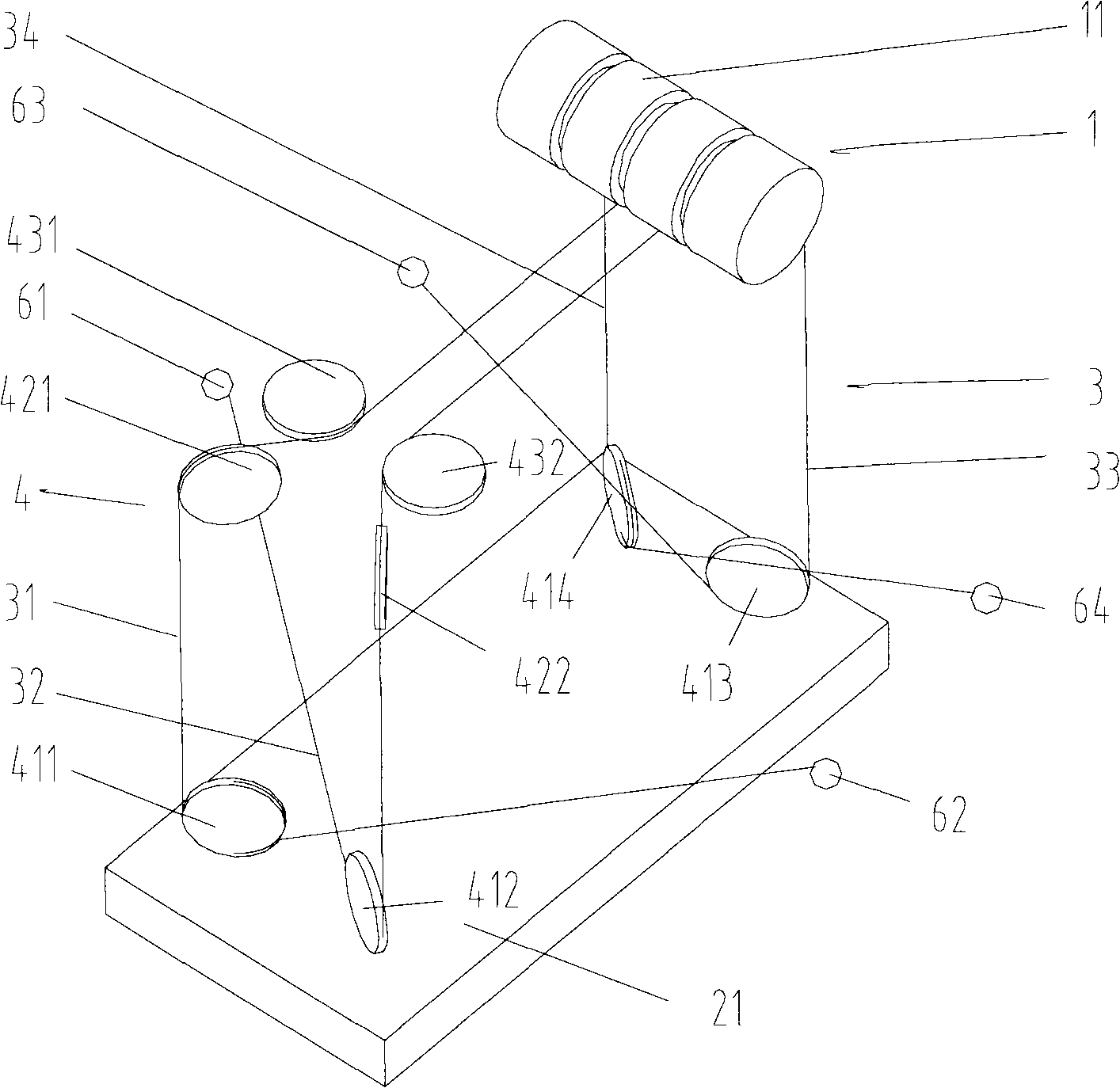
[0026] see figure 2 , which is a schematic structural diagram of the first embodiment of the present invention. It includes: a drum set 1, a spreader upper frame 21, a pulley block 4, and a wire rope set 3 wound on the drum set 1 and the pulley block 4.

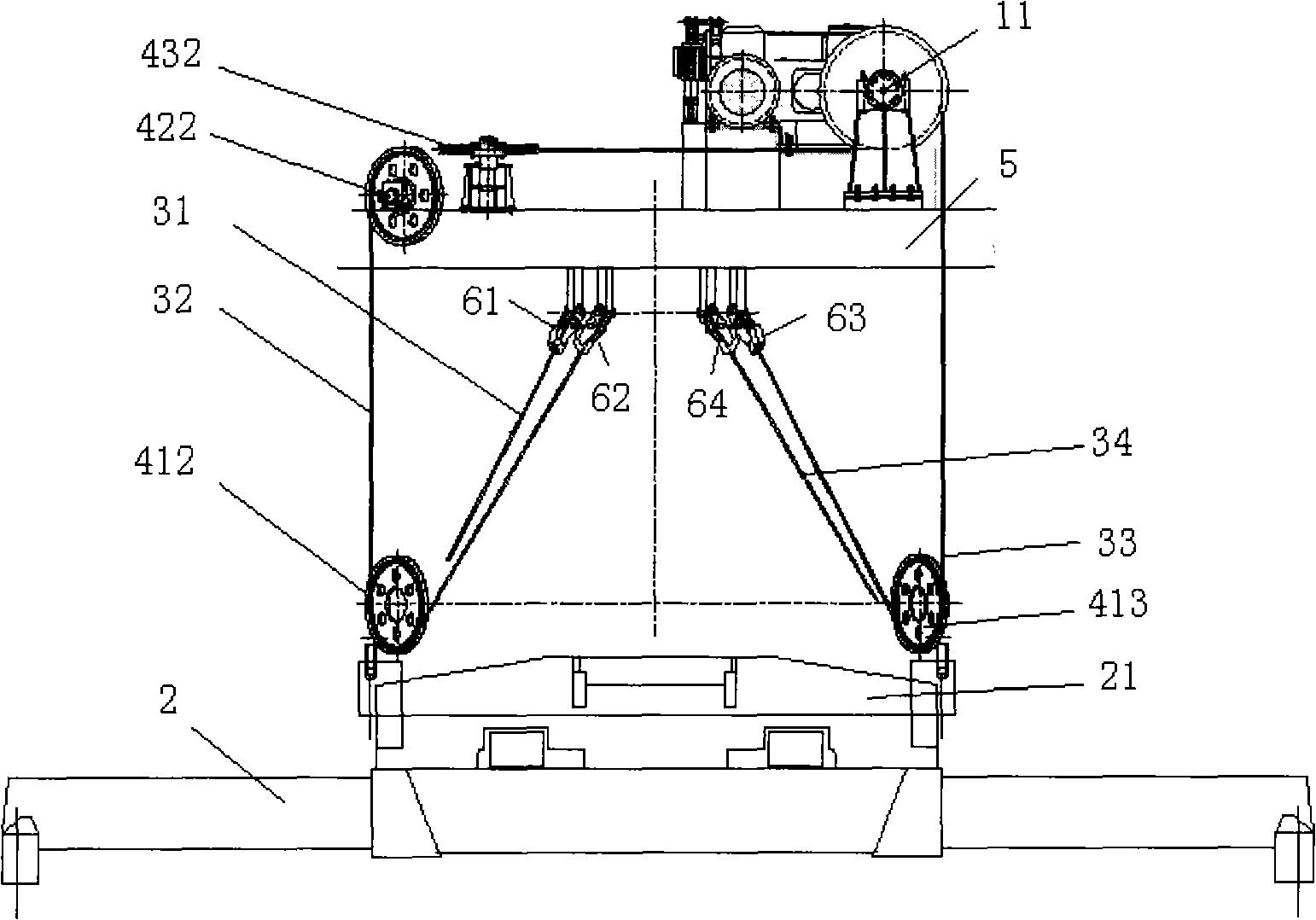
[0027] See also image 3 , Figure 4 ,in: image 3 is the front view of the first embodiment of the present invention; Figure 4 It is a left view of the first embodiment of the present invention, in which a brake 7 and a speed reducer 8 are marked, which can brake or decelerate the trolley.

[0028] The reel set 1, including the reel 11, is installed on one end of the trolley frame 5, and its central axis is parallel to the moving direction of the trolley.

[0029] The spreader upper frame 21 can be fixed above the spreader 2, and the movement conditions between the two are the same. ...


PUM


Abstract

The invention discloses a spreader stabilizing mechanism of a container gantry crane, comprising a drum group, a pulley block, a spreader upper frame and a steel wire rope group wound on the drum group and the pulley block; the steel wire rope forms four congruent inverse triangles at the space between the spreader upper frame and a pulley frame; the bottom points of the four inverse triangles are distributed at the four corners of the spreader upper frame symmetrically; included angles which are formed by the planes of the four inverse triangles and the moving direction of a cart and a trolley are all acute angles. Therefore, in the moving direction of the cart and the trolley, the motion damping of the four space triangles exists, thus reducing the swing of the spreader; when the load of the spreader is not balance and the swing of opposite angles is generated, namely, twisting and vibration are generated, the space triangle forms the motion damping in the diagonal direction of the upper surface of the spreader upper frame and forms damping component in three directions of the space, thus offsetting the swing of the opposite angles. The invention has simple structure, convenient maintenance and use and high safe reliability.

Description

technical field [0001] The invention relates to the field of cranes, in particular to an anti-sway mechanism for a spreader of a container gantry crane. Background technique [0002] The container gantry crane is the main loading and unloading equipment of the container terminal. With the rapid development of the container transportation industry today, how to improve its operation efficiency is an important issue that needs to be studied by various terminals and ports. Usually, under the conditions of site setting and equipment dimensions, the operating efficiency of container cranes is related to factors such as the driver's proficiency in operation, the structural parameters of crane carts and trolleys, and braking characteristics. Since each container to be lifted is not the same, the quality of the container operation depends largely on the experience of the driver. In addition, there are unpredictable operating inertia and wind loads, which cause the spreader and cont...

Claims


Application Information

Patent Timeline
Patent Type & Authority Applications(China)
IPC IPC(8): B66C13/06B66C17/20
Inventor 彭国成李翠英张寒张志国吴乐尧
Owner SANY MARINE HEAVY IND
Why Eureka
Try Eureka