Magnetic resolver

A solver, magnetic technology, applied in the field of magnetic solver, can solve the problems of lack of resolution and accuracy of detecting rotation angle, undisclosed form of salient pole and rotor core position relationship, etc.

Active Publication Date: 2009-01-14
TOYOTA JIDOSHA KK +1
View PDF1 Cites 7 Cited by
  • Summary
  • Abstract
  • Description
  • Claims
  • Application Information

AI Technical Summary

Problems solved by technology

[0005] In this regard, although the specific configuration of the outline of the rotor core is described in JP 5-3921, the form of the salient poles, the relationship between the form of the salient poles and the form of the rotor core, and the relat

Method used


Image

  • Magnetic resolver
  • Magnetic resolver
  • Magnetic resolver

Examples


Embodiment Construction

[0031] Embodiments of the present invention will be described below with reference to the accompanying drawings.

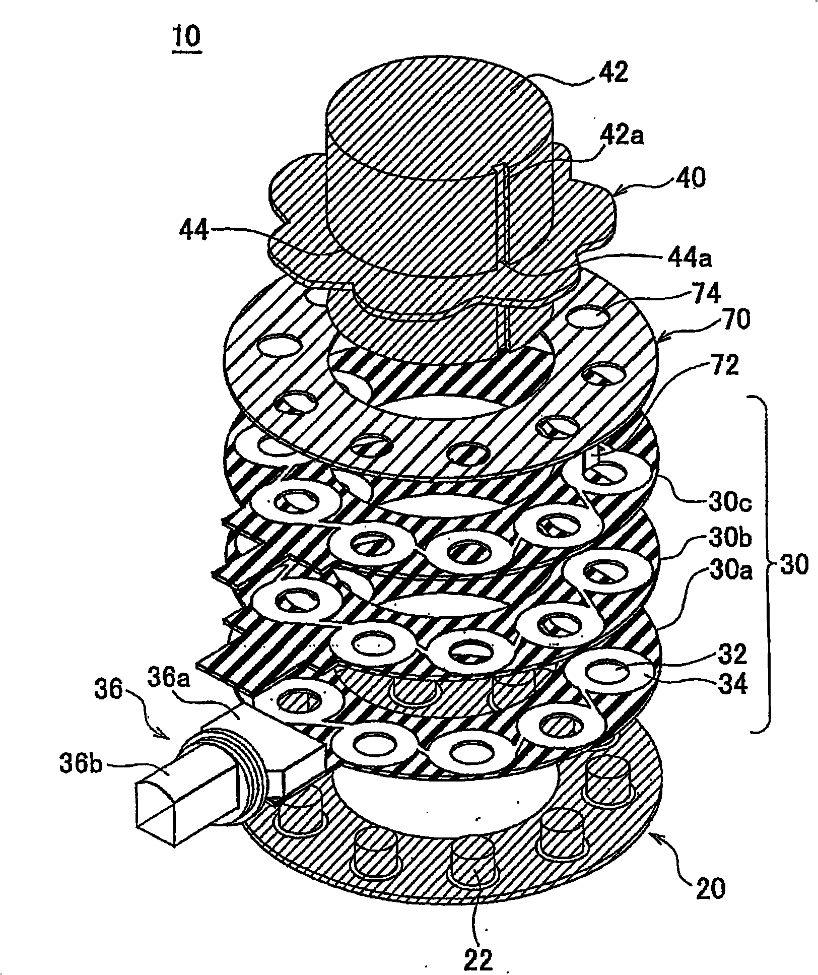
[0032] figure 1 is an exploded perspective view showing an embodiment of a magnetic resolver according to the present invention. In the description, "above" does not indicate a vertically upward direction in a state where the magnetic resolver is installed, but indicates that the rotor part exists relative to the stator part along the rotation axis regardless of the orientation of the magnetic resolver installed. direction. In this description and the appended claims, "radius" of a rotor means the distance between a reasonably determined center of the rotor and a point on the circumference of the rotor. Such a center includes the center circle of the profile change area described later or the center of the pitch circle of the core body, or the rotation center of the rotor. In the embodiments described below, these centers coincide with each other.

[0033] The...


PUM


Abstract

A magnetic resolver includes: a plurality of columnar cores disposed on an annular plate; a coil portion disposed around each of the columnar cores; and an annular rotor having a sinusoidal profile that rotates in a plane parallel to the top faces of the columnar cores around a rotation axis that passes through the center of the annular plate. The coil portion may be formed of a patterned coil formed on an annular substrate that has a plurality of through holes made therein through which the plurality of cores are passed, the patterned coil being formed around the through hole.

Description

technical field [0001] The invention relates to a magnetic resolver for detecting the rotation angle of a rotor. Background technique [0002] A conventional magnetic solver generally includes a rotatable rotor core, a stator core, and a thin-film coil. The stator core has two stator plates clamping the rotor core from top to bottom and has raised salient poles arranged along the circumference of the stator core. A thin film coil is wound around each salient pole of the stator core. The magnetic resolver detects the rotation angle of the rotor core by using the induction of the coil as a function of the rotation angle of the rotor core (see, for example, Japanese Utility Model Application Publication No. 5-3921 ("JP5-3921"). [0003] In the conventional resolver described above, a film-shaped coil formed in a pattern on a substrate is used, in contrast to the conventional resolver in which a wire is wound around a concave core on the stator facing the rotor in the radial di...

Claims


Application Information

Patent Timeline
IPC IPC(8): H02K24/00G01D5/20
Inventor 西口正幸关富勇治浜本洋志
Owner TOYOTA JIDOSHA KK
Why Eureka
Try Eureka