A test bench for simulating tool behavior at various positions on the cutter head

A technology for simulating a knife and a test bench, which is used in measuring devices, testing wear resistance, testing machinability, etc., to achieve the effect of reducing floor space, accurate test data, and saving space

Active Publication Date: 2021-09-07
SOUTHWEST JIAOTONG UNIV
View PDF8 Cites 0 Cited by
  • Summary
  • Abstract
  • Description
  • Claims
  • Application Information

AI Technical Summary

Problems solved by technology

[0006] Aiming at the problem that the linear cutting test bench in the prior art can only simulate the working conditions of the cutter with a larger installation radius during excavation, while the rotary test bench can only simulate the working conditions of a cutter with a smaller installation radius during excavation, the present invention provides a The test bench that can simulate the behavior of the cutter at each position of the cutter head is to enable the test bench to simulate the working conditions of the cutter during excavation under various installation radii, and to reduce the space occupied by the test bench

Method used


Image

  • A test bench for simulating tool behavior at various positions on the cutter head
  • A test bench for simulating tool behavior at various positions on the cutter head
  • A test bench for simulating tool behavior at various positions on the cutter head

Examples


Embodiment 1

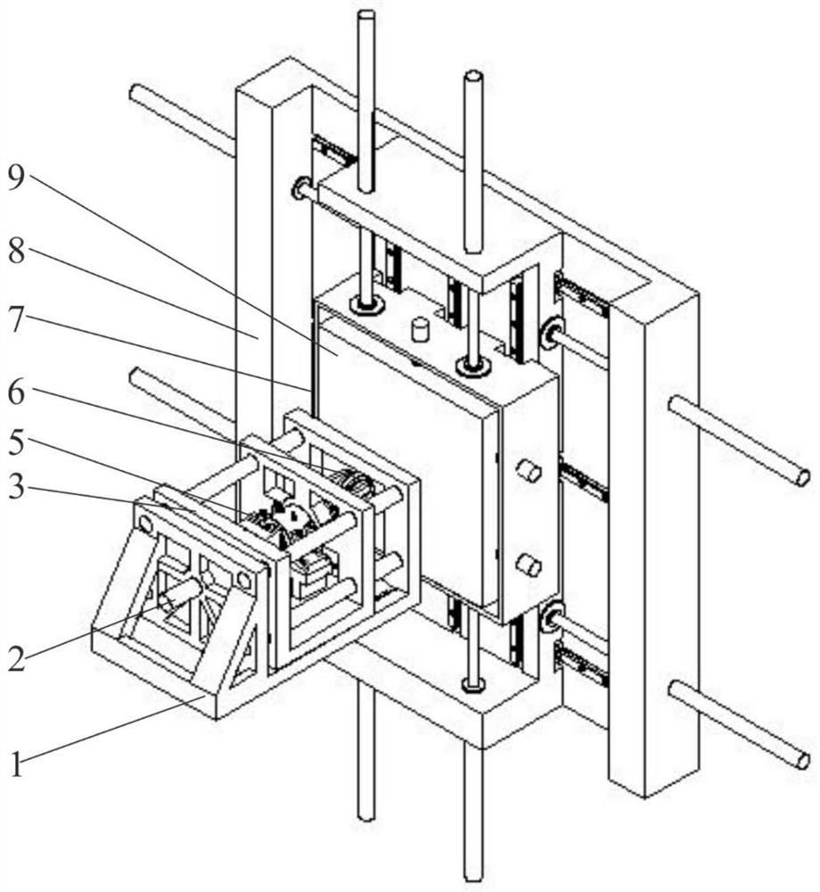
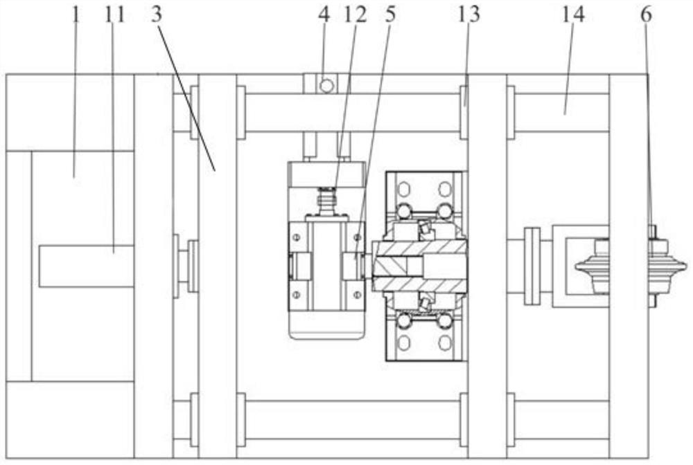
[0055] A simulation test of each station position of the tool cutter behavior, including horizontal and vertical base 8 of the base 1, a hydraulic propulsion system is provided with a transverse base 12, the hydraulic propulsion system 2 is connected to the tool griffe 6 system, provided with a rock box 8 on the longitudinal mobile system base 7, 9 is provided with a tank system on the rock of the rock tank 7 mobile system. Rock mobile tank system 7 to promote rock tank system 9 according to a set path, the tool according to a set path on the rock breaking rock sample. In this embodiment, the base 1 laterally arranged horizontally, vertically rock tank 7 is provided a mobile system, separate rock tank 7 is fixed to the mobile system on the foundation, the center and the center griffe tool system 6 coincides rock sample surface 904 perpendicular to the feeding direction of the tool system 6 griffe.

[0056] The rock mobile tank system 7 comprises a set of transverse rails 703 and l...

Embodiment 2

[0077]The present embodiment is substantially same as one embodiment aspect, except that: the angle with the seat 602, to install the tool belt angle, to simulate a knife edge or knife over excavation.

[0078] This embodiment confining pressures used to simulate different diameter cutter knife edge to overcut or condition, the same procedure as in Example particular test of a test procedure.

Embodiment 3

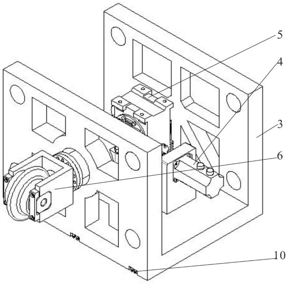
[0080] Substantially the same as one embodiment of the present embodiment aspect, except that: the griffe tool system comprising 6 to total three force sensors 606, connected by three and the plurality knife mounting plate 605 to the force sensor 606, the said multi-tool mounting plate 605 is connected to several three force sensors 601, the three-force sensor 601 is connected to the seat 602, the seat 602 has a bead 603 is bolted, a seat 603 is provided between the bead 602 and there are 604 knives.

[0081] In this embodiment, the multi-blade attachment slot defines a T-shaped upper plate 605, the three force sensor 601 with the T-slot slidably connected and fixed, the pitch of the blade according to the needs of the experiment by T-bolts stepless adjustment.


PUM


Abstract

The invention belongs to the technical field of a shield tunnel boring machine cutter behavior simulation test bench, and in particular relates to a test bench capable of simulating the cutter behavior at each position of a cutterhead, which solves the problem that the linear cutting test bench in the prior art cannot simulate various installation radius cutters. The problem of working conditions during excavation. The technical solution of the present invention is: comprising a horizontal base and a vertical base, the horizontal base is provided with a hydraulic propulsion system, the hydraulic propulsion system is connected with a knife box cutter system, and the vertical base is provided with a rock box A moving system, the rock box moving system is provided with a rock box system, and the rock box system corresponds to the position of the tool box cutter system. The invention drives the rock sample to move in the vertical plane, and fits circles or arcs with different radii, thereby simulating the rock-breaking working conditions of cutters with different installation radii. working conditions.

Description

Technical field [0001] The present invention belongs to the field of tool behavior simulation test rig shield tunneling machine, particularly relates to a respective position of the tool behavior simulation test bench cutter. Background technique [0002] Shield tunnel boring machine, tunnel boring is a special construction machinery, excavation and lining a safe, fast driving speed; forward, unearthed, assembled lining the whole process can be automated operation, low labor intensity of construction; does not affect the ground transportation and facilities, while not affecting underground pipelines and other facilities; does not affect shipping through the river, the construction season is not affected by wind and rain and other weather conditions, construction and other advantages of no noise and disturbance, has been widely used in railway, highway, municipal services, water and electricity and other tunnel project. According to statistics, the cost of tool wear caused directl...

Claims


Application Information

Patent Timeline
Patent Type & Authority Patents(China)
IPC IPC(8): G01N3/58G01N3/56G01N3/02
CPCG01N3/02G01N3/56G01N3/58G01N2203/0246G01N2203/0676
Inventor 莫继良勾斌段文军章龙管王好平孙瑞雪李贞范志勇周仲荣
Owner SOUTHWEST JIAOTONG UNIV
Why Eureka
Try Eureka