Dimmer

A dimmer and dimming technology, which is applied in the field of dimmers, can solve problems such as damage, deformation of the claw part or the claw receiving part, and achieve the effect of reducing deformation or damage, and reducing deformation or damage

Active Publication Date: 2009-01-21
PANASONIC CORP
View PDF1 Cites 3 Cited by
  • Summary
  • Abstract
  • Description
  • Claims
  • Application Information

AI Technical Summary

Problems solved by technology

However, with this configuration, a strong force is required when coupling the cover and body together
In addition, there is a possibility that the knuckle part or the knuckle receiving part is deformed or damaged during the coupling process

Method used


Image

  • Dimmer
  • Dimmer
  • Dimmer

Examples


Embodiment Construction

[0032] Below, will target Figures 1 to 6 The embodiments illustrated in describe the invention, Figures 1 to 6 Forms part of the Examples.

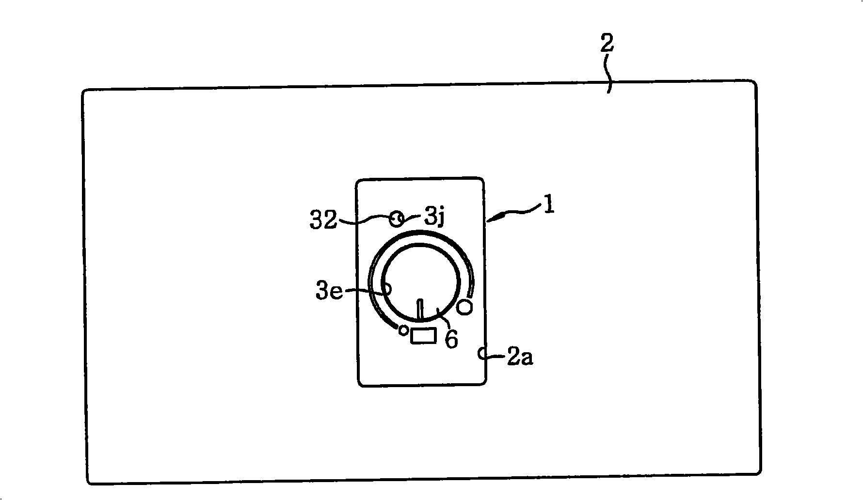
[0033] like figure 1 As shown in , the dimmer 1 is assembled to the panel 2 via a coupling frame (not shown). The panel 2 is in the shape of a rectangular plate and has an exposure hole 2a formed in its central area. The dimmer 1 is fixed to a wall (not shown) or the like in such a state that its front surface is exposed to the outside through the exposure hole 2 a. Furthermore, the front surface of the dimmer 1 forms a rectangular shape when viewed from the front side. In this embodiment, the dimmer 1 is fixed in place in such a way that its shorter side extends horizontally.

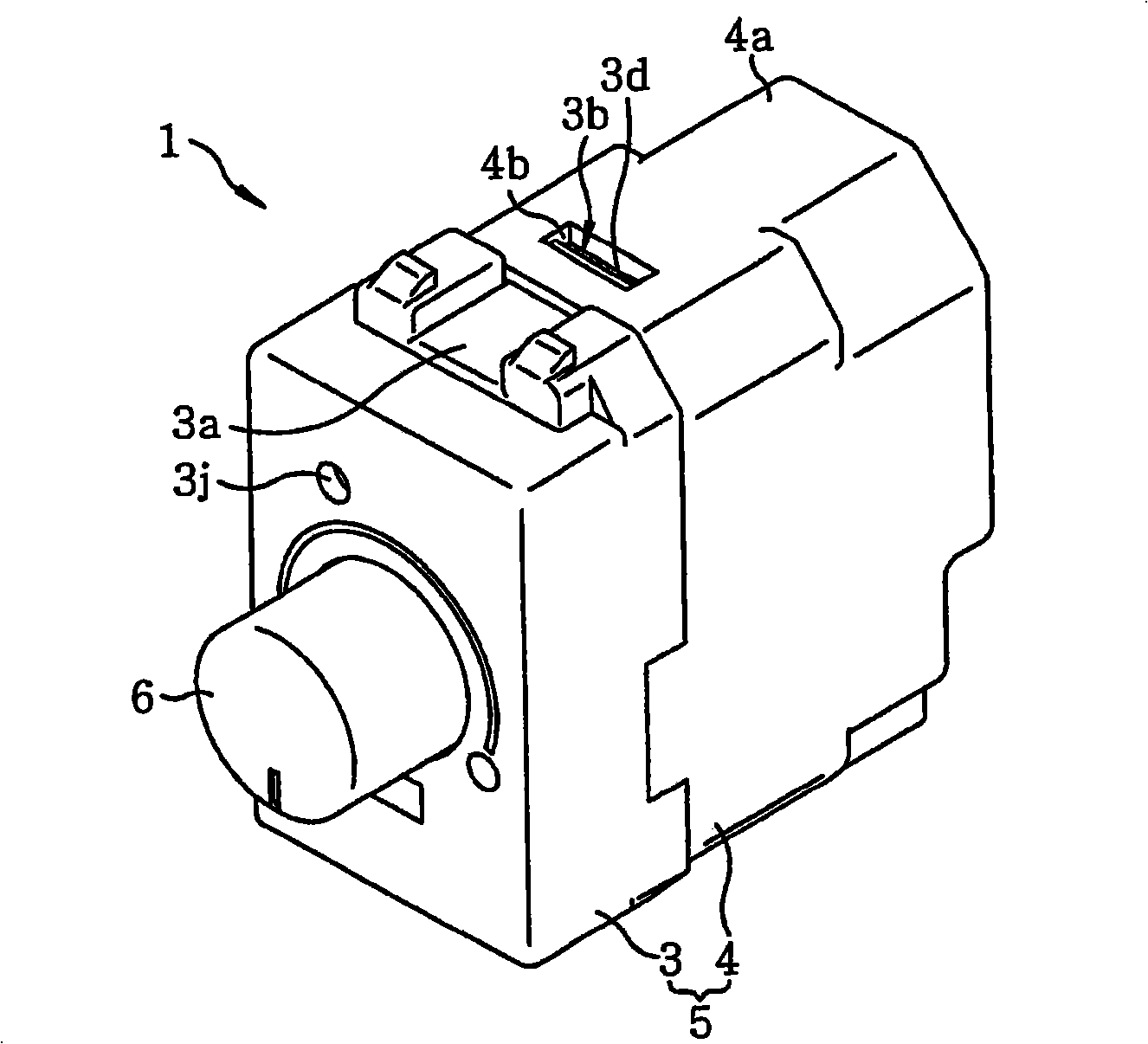
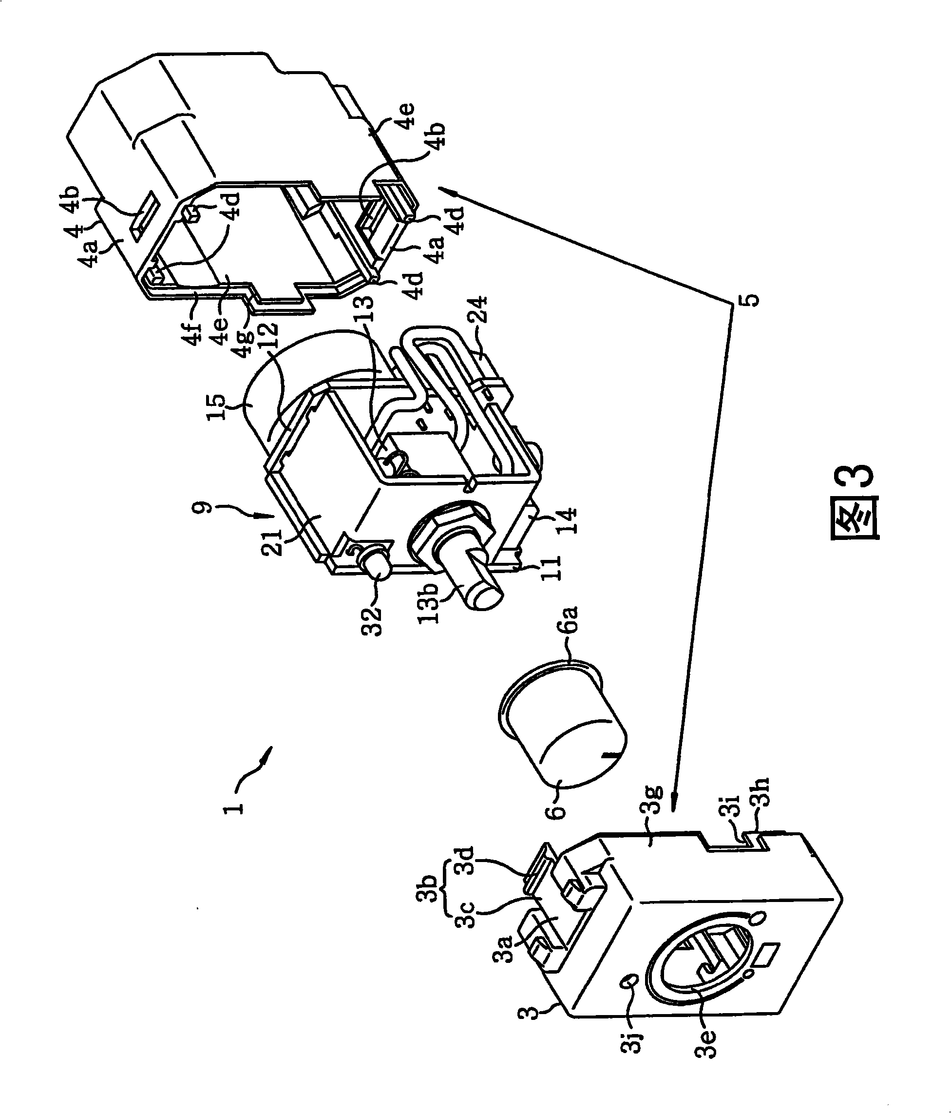
[0034] refer to figure 2 and 3, the dimmer 1 includes a box-type case 5 formed by a front cover 3 and a rear body 4, an operation knob 6 provided on the front surface (cover 3) of the case 5, and a plurality of circuits housed in the case 5. The circuit ...


PUM


Abstract

The invention relates to a dimmer, which comprises: a box shaped shell having a cover and a main body coupled to each other by an alcula and an alcula container; an operation knob disposed on the front surface of the shell; and multiple circuit devices contained in the shell. The circuit devices form a lightness regulating control circuit used for responding to the knob operation to regulate the lightness of the light loads. A pair of coupled concavo part and convex part are disposed on the cover and the main body near the alcula and the alcula container; and the cover and the main body can move relative to each other at least in three of the four orthogonal directions by limited observation in the front-rear direction while the cover and the main body is coupled.

Description

technical field [0001] The present invention relates to dimmers for adjusting the brightness of lamps such as incandescent lamps. Background technique [0002] Conventionally, a dimmer is arranged between an AC power source such as a commercial power source and a lamp such as an incandescent lamp to perform a dimming operation of a lamp load, an example of which is disclosed in Japanese Patent No. 3700329. [0003] The dimmer includes a box-shaped housing, an operating knob arranged on the front surface of the housing, and a plurality of circuit devices accommodated in the housing. The circuit devices constitute a dimming control circuit, and the dimming control circuit is used to operate the operating knob. Adjusts the brightness of the lamp load. The housing of the dimmer includes a front cover on which an operation knob is provided and a rear body. The front cover and the rear body are coupled into a box-like shape through their claw portions and claw receiving portions...

Claims


Application Information

Patent Timeline
IPC IPC(8): F21V23/00H05B39/04F21Y101/00
CPCY02B20/14Y02B20/00
Inventor 泷村亘向井达哉森志朗秋成芳范福尾尚纪三宅智裕
Owner PANASONIC CORP
Why Eureka
Try Eureka