Compression sleeve splitter and removal tool

a compression sleeve and tool technology, applied in the field of plumbing tools, can solve the problems of affecting the operation of the pipe, and requiring replacement with a new valve, so as to facilitate the removal of the ferrule and mitigate damage or deformation of the pipe

Active Publication Date: 2012-07-03
HUFFER BRIAN J +1
View PDF14 Cites 1 Cited by
  • Summary
  • Abstract
  • Description
  • Claims
  • Application Information

AI Technical Summary

Benefits of technology

[0014]It is contemplated that the splitting tool may facilitate removal of the ferrule from the pipe by piercing the ferrule. In this manner, the engagement between the ferrule and the pipe may be loosened. The splitting tool may also provide support to the inner wall of the pipe to mitigate damage or deformation to the pipe. Furthermore, the splitting tool may be used to remove the ferrule from the pipe without cutting the pipe. In this manner, the length of the pipe may be preserved.

Problems solved by technology

Over time, the valve may break down and require replacement with a new valve.
If the new valve is connected to the existing nut and ferrule, a fluid-tight seal may not be achieved.
Removing the ferrule from the pipe to allow a replacement valve or fitting to be connected can prove to be difficult.
However, after cutting the pipe, the remaining portion of pipe may be too short to connect with a replacement valve or fitting.
Furthermore, cutting the pipe may make re-connecting the other end of the valve to the adjacent pipe very difficult.
The welding of the new pipe is expensive and time consuming.
Therefore, prior art techniques are used to pull the ferrule off of the pipe in an attempt to avoid the cutting of the pipe, however, such tools may damage the pipe.
In addition, such ferule pulling tools are bulky and it may be difficult to operate such tools in small confines, where plumbing valves are typically hidden from view.

Method used


Image

  • Compression sleeve splitter and removal tool
  • Compression sleeve splitter and removal tool
  • Compression sleeve splitter and removal tool

Examples


Embodiment Construction

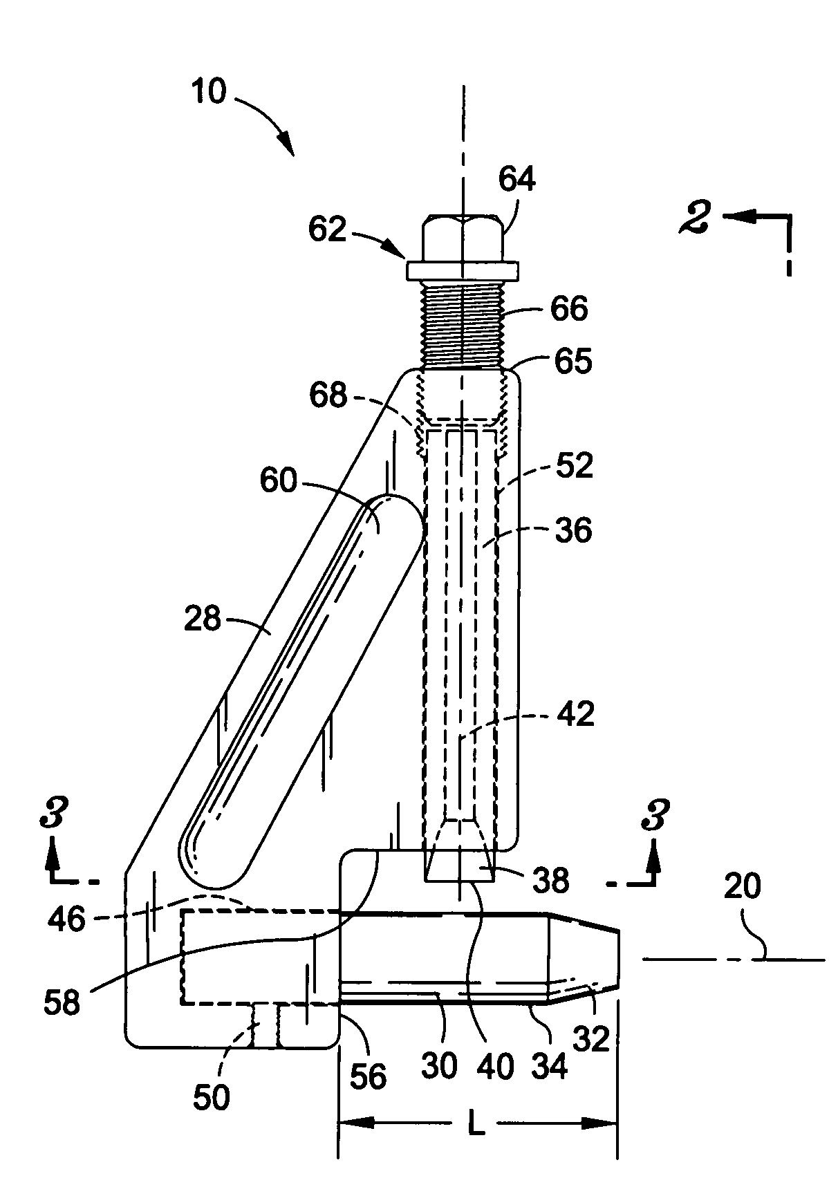
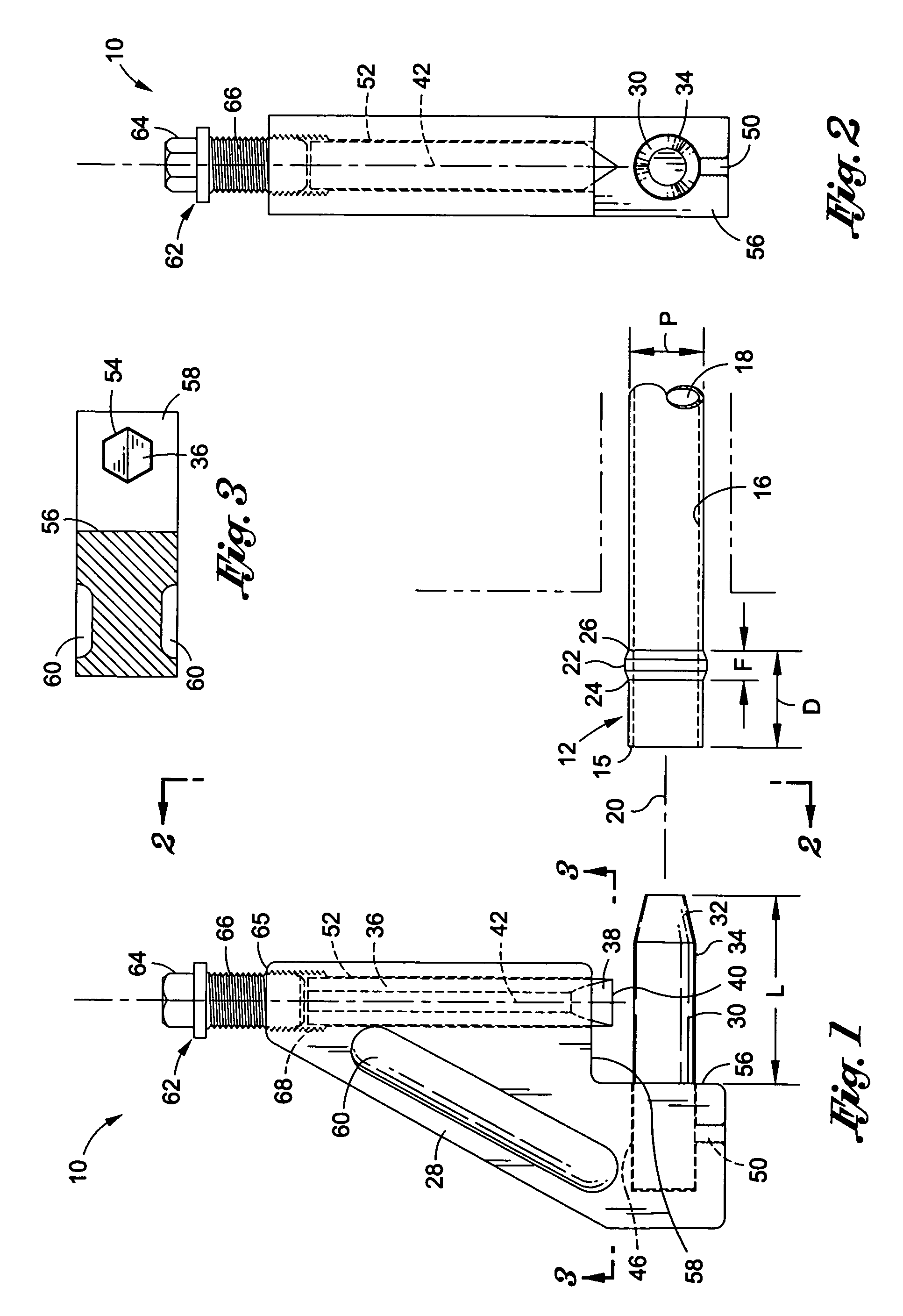
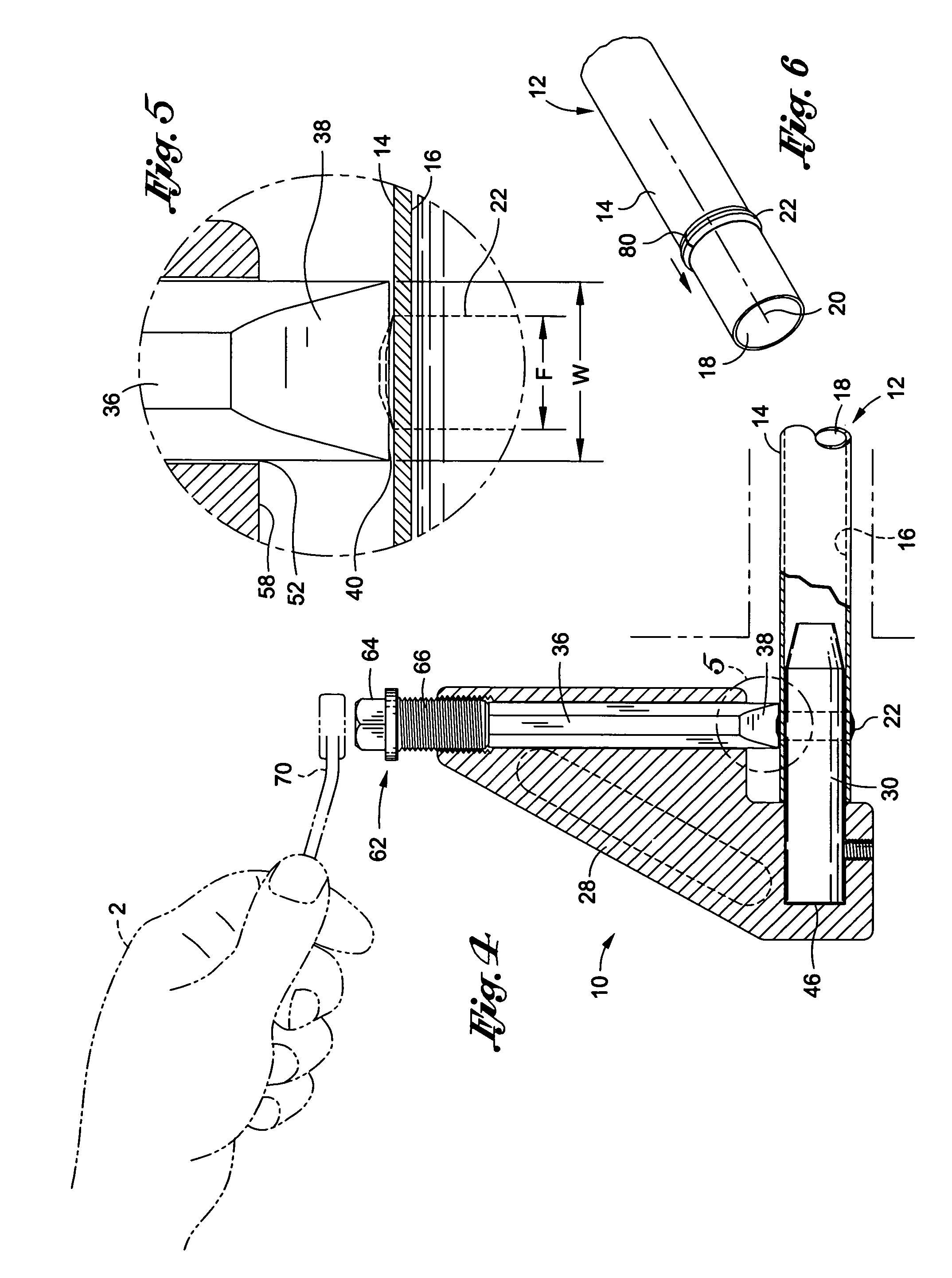
[0027]Referring now to the drawings wherein the showings are for purposes of illustrating a preferred embodiment of the present invention only, and not for purposes of limiting the same, FIGS. 1-6 illustrate a splitting tool 10 constructed in accordance with an embodiment of the present invention. The splitting tool 10 may be used to pierce the ferrule 22 or form a crack 80 within a ferrule 22 disposed on a pipe 12. Once the ferrule 22 is pierced or cracked, the engagement between the ferrule 22 and the pipe 12 is typically loosened to facilitate removal of the ferrule 22 from the pipe 12.

[0028]As used herein, a pipe 12 refers to an elongate, hollow member for transmitting fluid therein. The pipe 12 defines a longitudinal pipe axis 20. The pipe 12 includes an outer wall 14 and an inner wall 16 that defines a pipe channel 18. It is understood that a residence or commercial structure may include a plumbing system having a network of interconnected pipes 12. A ferrule 22 is an element ...


PUM

PropertyMeasurementUnit
forceaaaaaaaaaa
cutting forceaaaaaaaaaa
diameteraaaaaaaaaa

Abstract

There is provided a splitting tool for use with a pipe defining a longitudinal pipe axis. The pipe includes an outer wall and an inner wall defining a pipe channel. A ferrule is circumferentially disposed about the outer wall. The splitting tool includes a pipe support member defining an outer periphery that is substantially complimentary in shape to the inner wall. The pipe support member is insertable within the pipe channel to extend at least through the ferrule and to provide radial support to the inner wall. The splitting tool additionally includes a splitter member operatively connected to the pipe support member. The splitter member defines a longitudinal splitting axis that is substantially perpendicular to the pipe axis when the pipe support member is inserted within the pipe channel. The splitter member is moveable along the splitting axis to radially engage with and pierce the ferrule.

Description

CROSS-REFERENCE TO RELATED APPLICATIONS[0001](Not Applicable)STATEMENT RE: FEDERALLY SPONSORED RESEARCH / DEVELOPMENT[0002](Not Applicable)BACKGROUND OF THE INVENTION[0003]1. Field of the Invention[0004]The present invention relates generally to plumbing tools and more particularly, to a plumbing tool for removing a compression fitting from a pipe.[0005]2. Description of the Related Art[0006]A plumbing system for a building or house typically includes a network of interconnected pipes distributed throughout the structure. It is generally desirable to control the flow of fluid through the pipes with valves. Accordingly, one or more valves may be connected to the pipes to control the flow of fluid therethrough. In order to form a fluid-tight seal between the valve and the pipe, a compression fitting or ferrule is typically disposed within the pipe-valve connection.[0007]As used herein, a ferrule refers to a band, typically formed of a metallic material, that is circumferentially dispose...

Claims


Application Information

Patent Timeline
Patent Type & Authority Patents(United States)
IPC IPC(8): B23P19/04
CPCB23D21/02B25B27/10B26D3/001Y10T29/53987Y10T29/53843Y10T29/53909
Inventor HUFFER, BRIAN J.EBNER, EMMETT J.
Owner HUFFER BRIAN J
Why Eureka
Try Eureka