Wind-velocity indicator support

An anemometer, horizontal technology, applied in the directions of instruments, speed/acceleration/electric shock meter detailed information, speed/acceleration/shock measurement, etc., can solve the problems affecting the accuracy of the test structure, inconvenient test work, etc., and achieve a wide range of engineering application prospects , improve stability and save costs

Inactive Publication Date: 2009-01-21
SOUTHEAST UNIV
View PDF0 Cites 9 Cited by
  • Summary
  • Abstract
  • Description
  • Claims
  • Application Information

AI Technical Summary

Problems solved by technology

Most structures do not have anemometer brackets built in advance during structural construction. Therefore, in the current on-site wind measurement work, most of them make a simple support according to their respective test needs, or bind it directly to the structure. It not only affects the accuracy of the test structure, but also brings great inconvenience to the test work

Method used


Image

  • Wind-velocity indicator support
  • Wind-velocity indicator support
  • Wind-velocity indicator support

Examples


Embodiment Construction

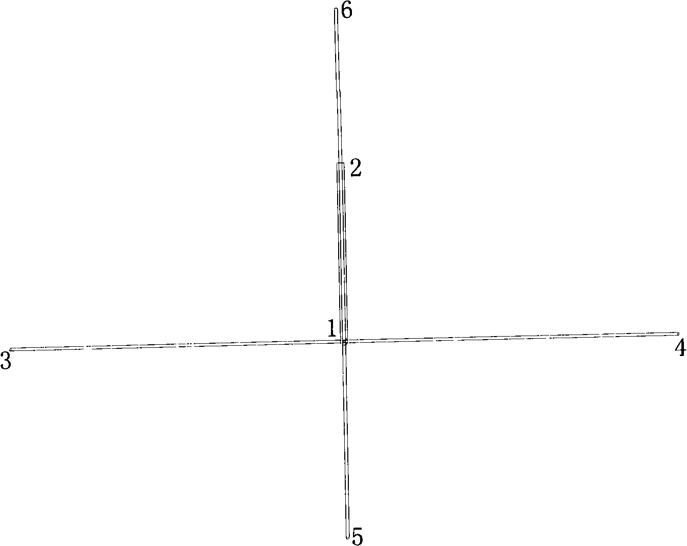
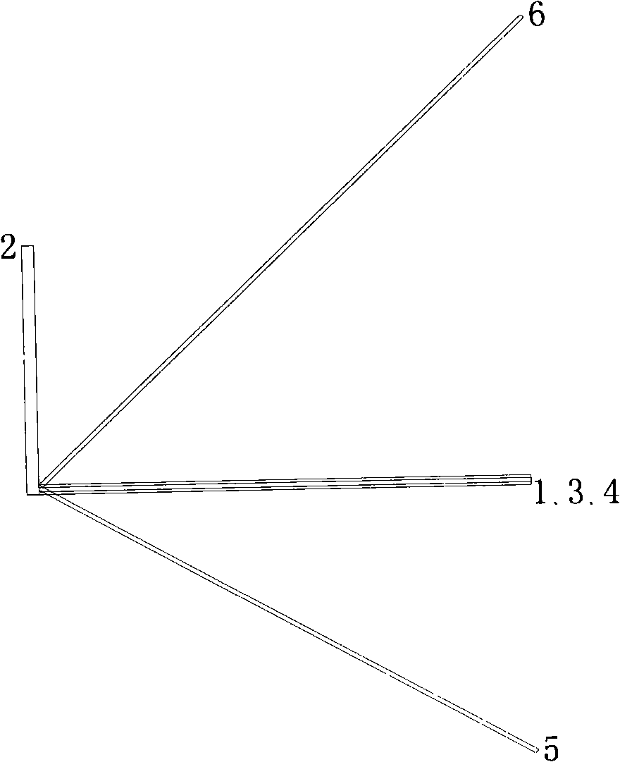
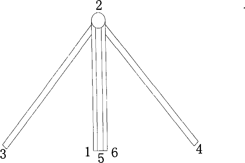
[0024] The novel anemometer bracket of the present invention includes six stretchable rods, which are respectively a horizontal main rod 1, a vertical main rod 2, a horizontal left support rod 3, a horizontal right support rod 4, a vertical lower support rod 5, and a vertical upper support rod. Tie rod 6. Among them, in the horizontal plane, the horizontal main rod is fixed on the outside of the structure, and the horizontal left strut and the horizontal right strut are connected to the extension end of the horizontal main rod; in the vertical plane, the vertical main rod is perpendicular to the horizontal main rod and extends At the end, the vertical lower support rod is located below the horizontal main rod, connecting the measured structure and the horizontal main rod, and the vertical upper rod is located above the horizontal main rod, connecting the measured structure and the horizontal main rod. The overall structure diagram of the support structure is shown in figure 1 ...


PUM


Abstract

The invention relates to a supporting stand of a wind-velocity indicator, which is formed by six telescopiform steel pipes through an installable/detachable connecting mode, wherein the six telescopiform steel pipes comprises a horizontal main rod, a vertical main rod, a horizontal left brace rod, a horizontal right brace rod, a vertical lower brace rod and a vertical upper link, wherein the horizontal main rod is fixed on the outer side of the supporting stand in a horizontal plane, the horizontal left brace rod and the horizontal right brace rod are connected on the extended end of the horizontal brace rod to improve the stability of the main rod in the horizontal plane, the vertical main rod is vertical to the extended end of the horizontal main rod in the vertical plane, the vertical lower brace rod is arranged on the lower portion of the horizontal brace rod, a measured structure and the horizontal main rod are connected, the vertical upper link is arranged on the upper portion of the horizontal main rod, and the measured structure and the horizontal main rod are connected to improve the stability of the main rods in the vertical plane. The supporting stand of a wind-velocity indicator must have wide prospect in engineering application as wind characteristic tests are regarded in the whole world.

Description

technical field [0001] The invention relates to a novel anemometer support, which is especially suitable for fixing various anemometers at selected test positions when testing the wind environment of a large-scale engineering structure in the field. Background technique [0002] Wind disaster is one of the most frequent natural disasters. In the 1980s, the statistics of the Munich Insurance Company of the Federal Republic of Germany on the natural disasters in western developed countries that lost more than US$100 million showed that the frequency of wind disasters was high and secondary disasters were large, and the number of wind disasters accounted for 51.4% of the total number of natural disasters. , economic losses accounted for 40.5% of the total losses of natural disasters. With the continuous development of production and construction, like other disaster losses, wind disaster losses are also increasing every year. Among all kinds of wind disaster losses, the damag...

Claims


Application Information

Patent Timeline
Patent Type & Authority Applications(China)
IPC IPC(8): G01P1/00
Inventor 王浩李爱群王晨谢静
Owner SOUTHEAST UNIV
Why Eureka
Try Eureka