

Automatic transfer switch electric appliance for moment parallel device
An automatic transfer switch and parallel connection technology, which is applied to electric switches, power devices inside switches, circuits, etc., can solve problems such as uninterruptible power supply, achieve continuous supply, increase service life, improve reliability and safety Effect
- Summary
- Abstract
- Description
- Claims
- Application Information
AI Technical Summary
Problems solved by technology
Method used
Image

Examples
Embodiment Construction
[0024] Below in conjunction with accompanying drawing, the present invention is described in further detail with preferred embodiment:
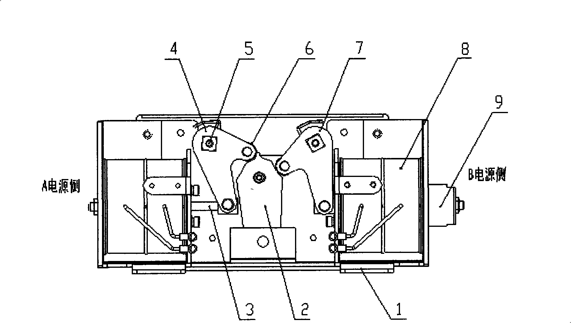
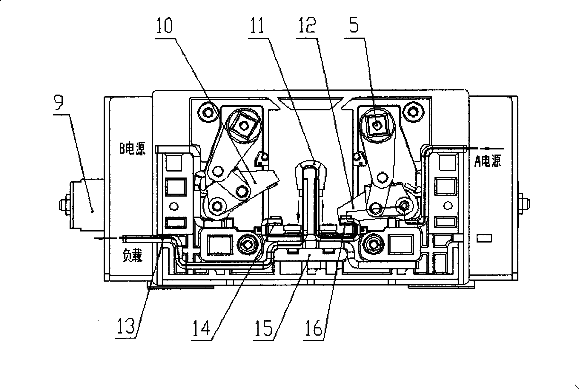
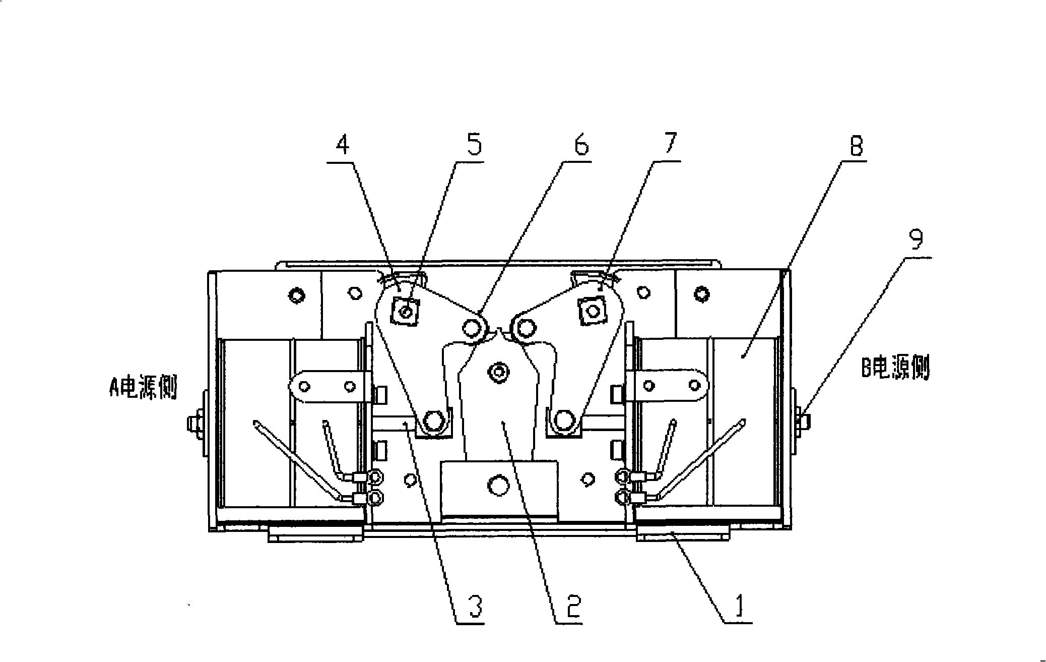
[0025] refer to figure 1 , figure 2 , image 3 , Figure 4 , Figure 5 , Figure 6 , Figure 7 , Figure 8 , the automatic transfer switch electrical appliance of the momentary parallel device, including the lock plate (2), the swing plate A (4), the swing plate B (7), the roller (6), the main shaft (5), the main support (1), the damper (17), electromagnet (8) and be connected on the electromagnet moving iron core and be provided with connecting rod (3), base (1) 5, moving contact A (10), moving contact B ( 12), static contact A (14), static contact B (16), load terminal (13), soft link (11), moving iron core (9).
[0026] The roller is arranged on the top of the swing plate, and cooperates with the cam surface on the lock plate (2), so that the movement of the swing plate and the lock plate becomes a rolling fit. When the rollers o...
PUM
 Abstract
Description
Claims
Application Information