Contactor falling-resistant device

A technology of anti-touch and moving contacts, which is applied in the field of low-voltage electrical equipment, can solve the problems of high manufacturing and installation precision, poor operation reliability, and high manufacturing difficulty, so as to achieve small movement resistance, improve operation reliability, and process molding easy effect

Inactive Publication Date: 2011-04-06
JIANGSU KAIFAN ELECTRICAL APPLIANCES
View PDF7 Cites 6 Cited by
  • Summary
  • Abstract
  • Description
  • Claims
  • Application Information

AI Technical Summary

Problems solved by technology

The existing new contact drop prevention device (such as US patent document US005313180A and Chinese patent 200610037996.9, etc.) is usually provided with a cam surface on the edge of the movable contact, and the positioning of the spring and the bayonet on the cam surface is used to realize the repulsion of the movable contact. Most of these structures have defects such as complex structure, high manufacturing difficulty, high manufacturing and installation precision requirements, and poor operational reliability.

Method used


Image

  • Contactor falling-resistant device
  • Contactor falling-resistant device
  • Contactor falling-resistant device

Examples


Embodiment Construction

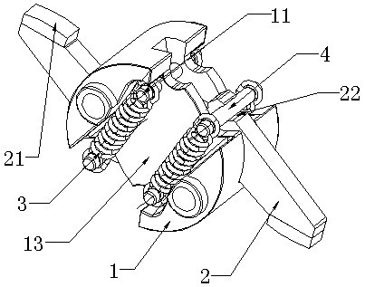
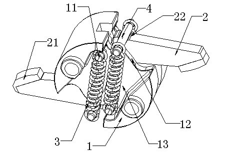
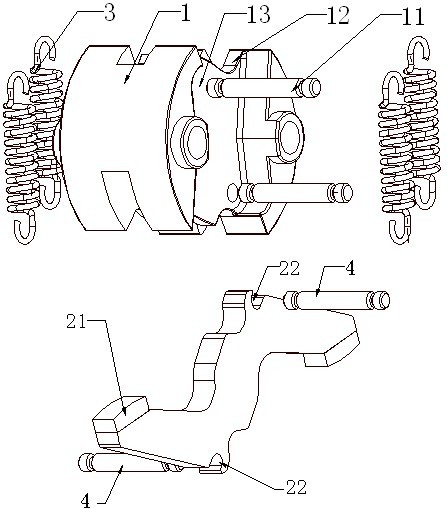
[0017] As shown in the figure, this new type of contactor drop prevention device includes a shaft body 1 and a moving contact 2 that runs through the inner cavity of the shaft body and can rotate around the center of the shaft body. The center of the moving contact 2 is symmetrical, and its front and rear ends are respectively provided A movable contact 21 corresponding to the upper and lower static contacts A contacts; a sliding groove 22 is respectively provided at the front and rear of the symmetrical center of the moving contact 2, and one of the sliding grooves 22 protrudes to both sides The two ends of each bayonet are drawn by a pair of extension springs 3 located outside the shaft body, and the fixed ends of the extension springs 3 are connected to the fixed pins 11 on both sides of the shaft body 1; the upper and lower sides of the shaft body Each edge is provided with a section of cam surface 12, and the cam surface is composed of two concave sections at both ends and...


PUM


Abstract

The invention belongs to low voltage electrical equipment, relating to a contactor falling-resistant device in a low-voltage circuit breaker. The contactor falling-resistant device comprises a spindle body and a moving contact, wherein the moving contact penetrates through the inner cavity of the spindle body from front to back and can rotate around the center of the spindle body; the moving contact is in central symmetry, the front and rear ends of the moving contact are respectively provided with a moving contact point which corresponds to fixed contact points at the upper and lower parts of the circuit breaker; the front and rear part of the centre of symmetry of the moving contact are respectively provided with a chute; each chute is internally provided with a bayonet lock which stretches out of the two sides; two ends of each bayonet lock are dragged by a pair of tension springs positioned outside the spindle body; the fixing ends of the tension springs are connected to fixing pins at two external sides of the spindle body; the upper and lower edges of the spindle body are respectively provided with a section of camming surface which is composed of two hollow sections at two ends and a hunch-up section in the middle; and the bayonet lock is always pressed on the camming surfaces under the action of the tension springs and can stay at the bottoms of the two hollow sections. The invention has simple structure and reliable action and is convenient to manufacture and install.

Description

technical field [0001] The invention belongs to low-voltage electrical equipment, and relates to a contact drop prevention device in a low-voltage circuit breaker. Background technique [0002] The rotating shaft part of a low-voltage circuit breaker usually includes a rotating shaft body driven by a circuit breaker operating mechanism and a movable contact installed on the rotating shaft body. During normal operation, the rotating shaft drives the moving contact to rotate to realize the opening and closing of the static contact of the circuit breaker. However, when the circuit breaker is over-current due to a fault such as a short circuit, the contact needs to be disconnected quickly, and the use of It takes a long time for the protection circuit of the operating mechanism to drive the rotating shaft to perform the opening action. Therefore, in order to ensure that the contacts can be disconnected quickly during overcurrent, the rotating shaft parts of the existing structu...

Claims


Application Information

Patent Timeline
Patent Type & Authority Applications(China)
IPC IPC(8): H01H1/20H01H1/50H01H71/00
Inventor 王华章李涛马丽萍钱兴勇郭强耿翔宇
Owner JIANGSU KAIFAN ELECTRICAL APPLIANCES
Why Eureka
Try Eureka