Methods for optimizing efficiency and durability of rotary drag bits and rotary drag bits designed for optimal efficiency and durability

A drill bit and drilling technology, applied in the field of rotary traction drill bits

Inactive Publication Date: 2009-01-21
BAKER HUGHES INC
View PDF0 Cites 8 Cited by
  • Summary
  • Abstract
  • Description
  • Claims
  • Application Information

AI Technical Summary

Problems solved by technology
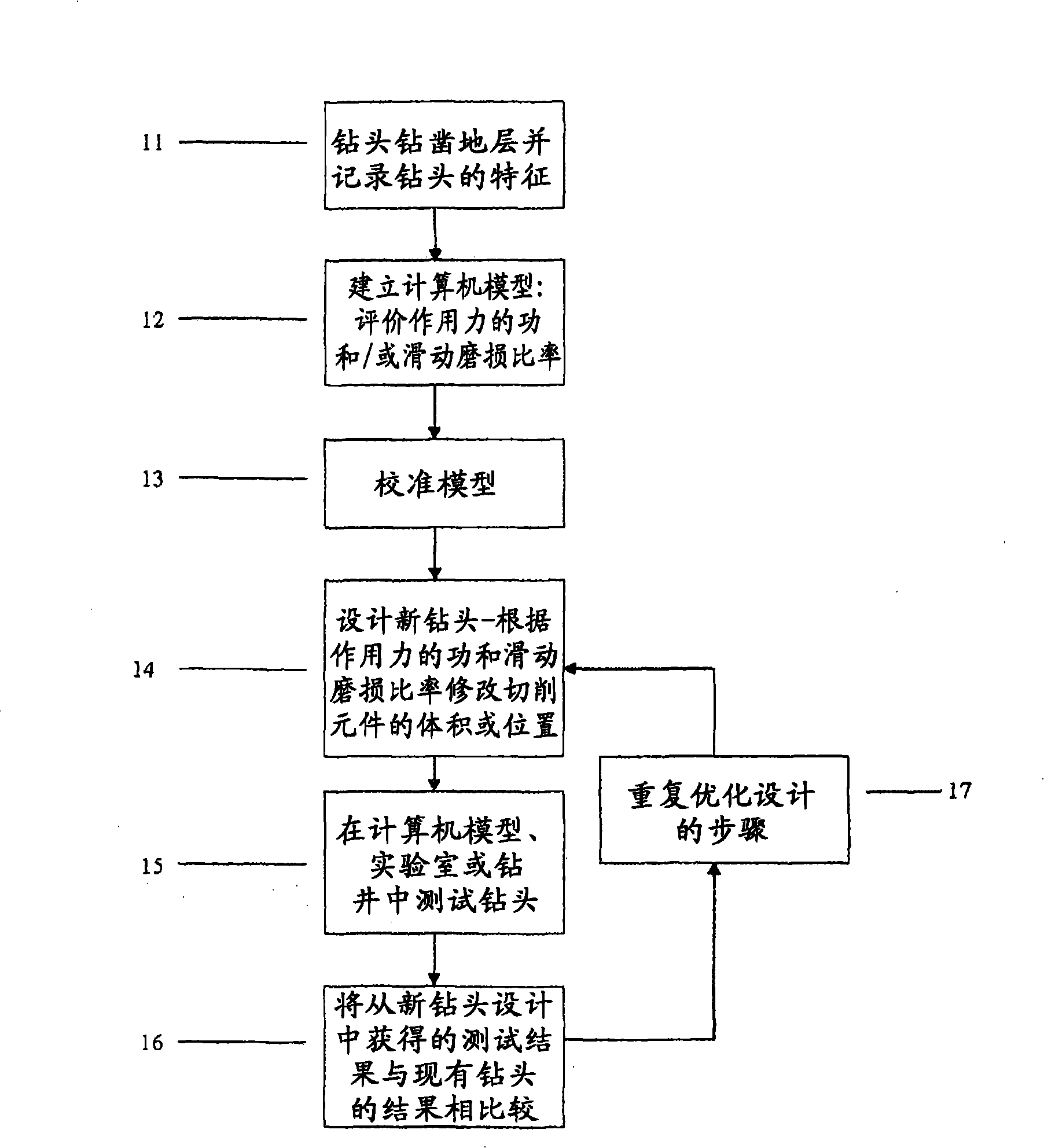
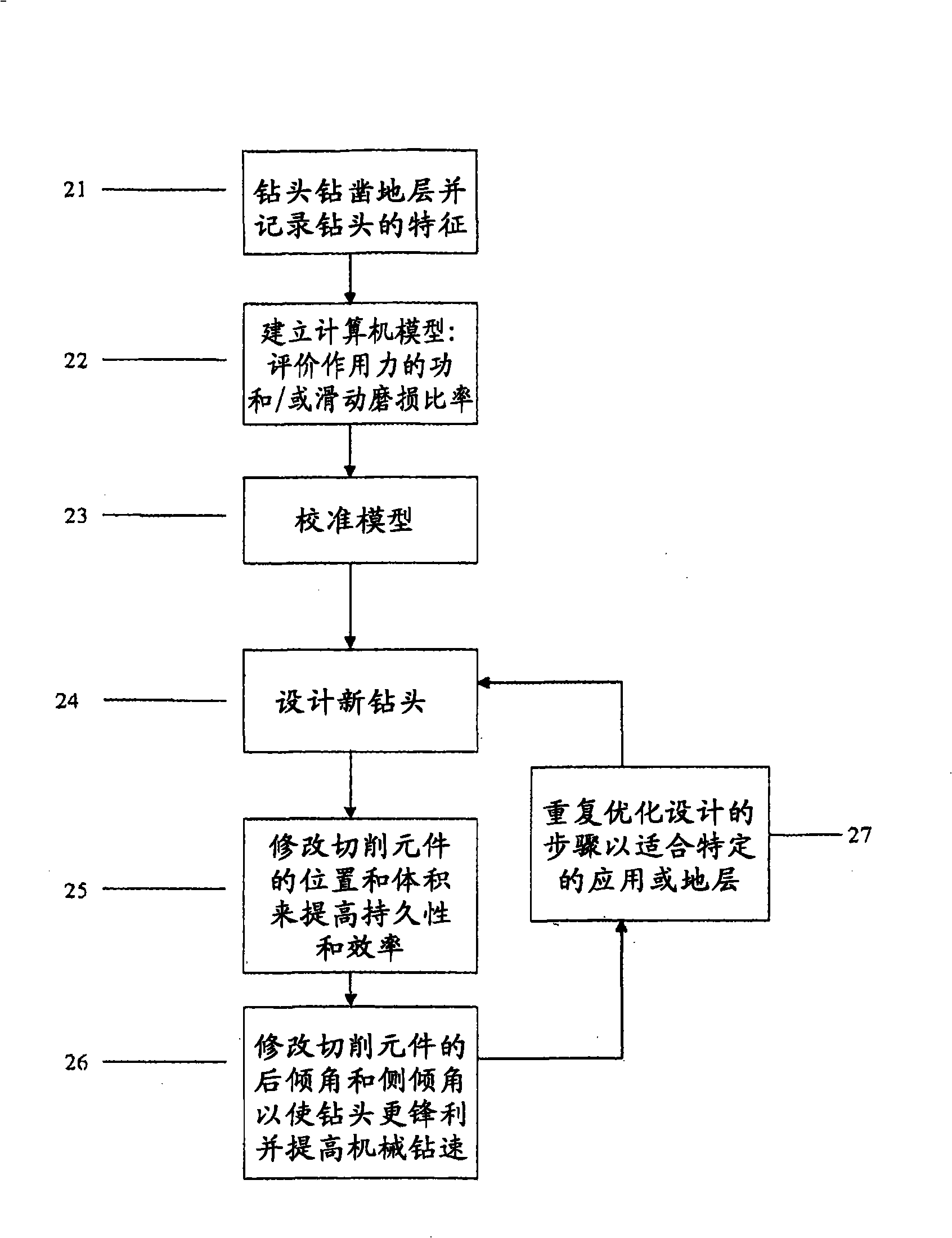
[0008] There is an unmet need for drill bit design methods where the work and sliding wear rates of the applied forces are relative to the volume and location of the cutting elements

Method used


Image

  • Methods for optimizing efficiency and durability of rotary drag bits and rotary drag bits designed for optimal efficiency and durability
  • Methods for optimizing efficiency and durability of rotary drag bits and rotary drag bits designed for optimal efficiency and durability
  • Methods for optimizing efficiency and durability of rotary drag bits and rotary drag bits designed for optimal efficiency and durability

Examples


example 1

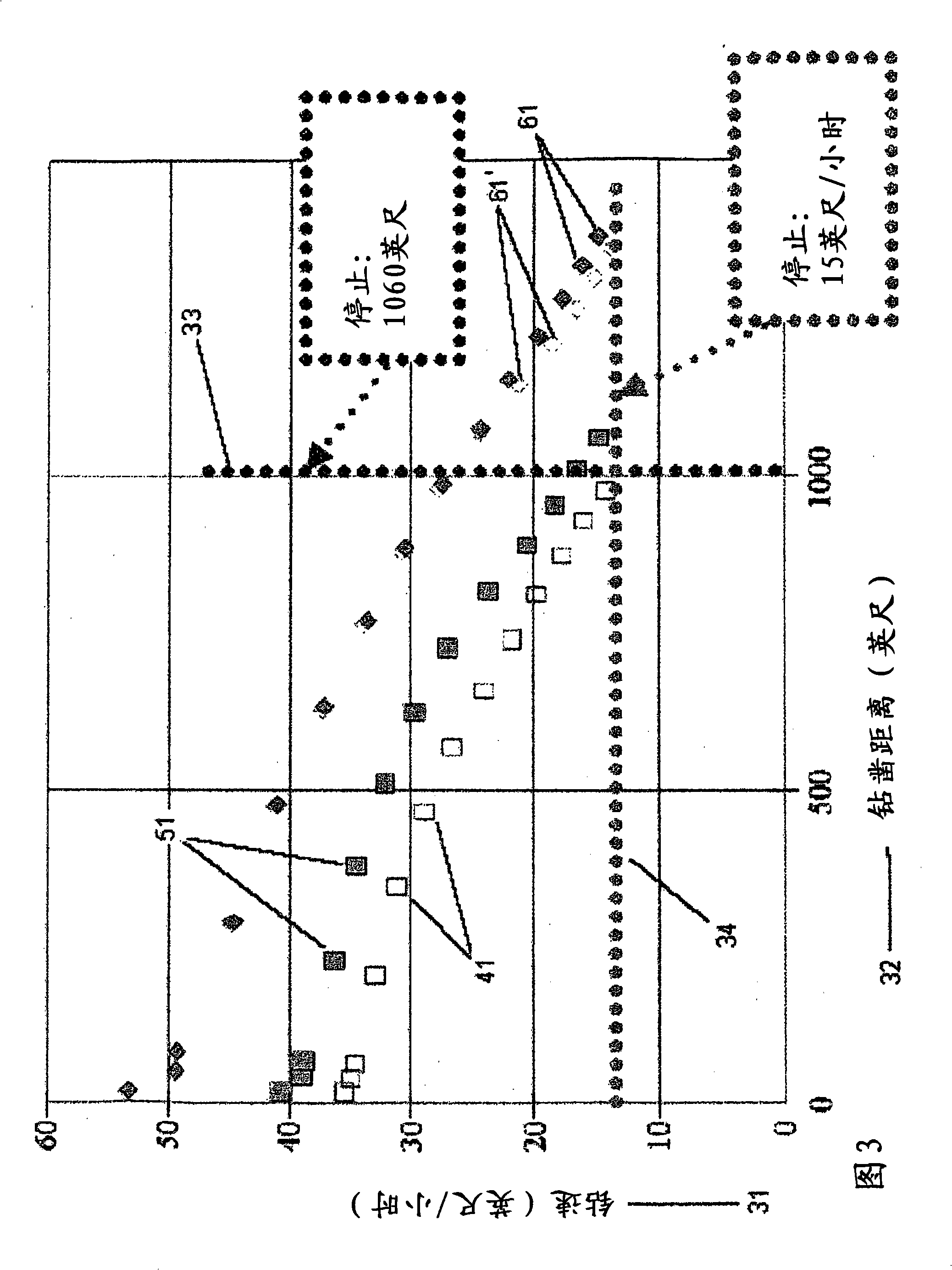
[0042] Several drill bits were evaluated according to the teachings of the present invention.

[0043] Figure 3 is an aggregated block of data collected in the field with existing bit designs and data from computer simulations of new bit designs. Existing drill bits drill into a given formation and collect data, including rate of penetration (ROP) and distance drilled. The Y-axis 31 represents the average rate of penetration (ROP) in feet per hour, while the X-axis 32 represents the distance drilled into the formation in feet. The X-axis 32 starts at 0 feet drill distance, which indicates that the drill bit has not drilled the formation, ie, the drill bit is new. The distance drilled by the bit increases linearly to the right along the X-axis 32 . Two standards are imposed on the graph, and the working performance of the drill bit is compared with this. The vertical dashed line 33 represents a total drilled distance of 1060 feet (323 meters), the distance that has been dril...

example 2

[0057] In another example of the method, Figures 4 and 8 provide representative examples showing axial views and contours of the cutting elements of two drill bits for which a computer model was built, and Figure 5 shows a third drill bit outline drawing. Figures 4 and 5 are as described above. Figure 8 is a diagrammatic representation of a Hughes Christensen drill bit model HC511Z. The drill bit 81 has a plurality of cutting elements 82 located on a plurality of cutting edges 83, visible in an axial view of the drill bit, as are a plurality of jets 84. The center of the bit is the cone 85 and the radially outermost of the bit is the gauge distance 86 or radial distance. Adjacent to the axial view of the drill bit 81 is a contour map 87 . The radial and axial positioning of each primary cutting element 82 is shown as it passes through the corresponding plane on the page of FIG. 8 . Two vertical lines 88 and 89 respectively represent the positions of the cutting elements 82...


PUM


Abstract

A method for evaluating existing drill bits and drill bit designs includes measuring several desired characteristics of a bit, including the wear experienced in drilling a formation, such as an actual formation or a simulated formation or a laboratory test fixture. A computer model may be used to evaluate the work-force and/or the sliding-wear rates that cutting elements of the bit experience as compared with the rate-of-penetration and/or durability of the bit. This information may be used to design a new drill bit, which may involve modification of the cutting elements {e.g., moving the location, volume (size and shape) or number of cutting elements from areas of the bit that receive lower work-force and sliding-wear rates to those areas that experience relatively greater work-force and sliding wear-rates.; This may permit the cutting elements to be oriented more aggressively relative to a formation to be drilled. Other parameters that may be optimized include the bit profile, blade count, hydraulics, or the like.

Description

[0001] related application [0002] This application claims priority to US Provisional Application 60 / 734571, filed November 8, 2005, the entire disclosure of which is incorporated herein by reference. technical field [0003] Field of the Invention: This invention relates to rotary traction drill bits and their operation for drilling subterranean formations. More specifically, the present invention relates to a method of designing such a drill bit for optimum performance by evaluating the work-force rate and sliding wear rate of the force of the cutting element on the drill bit, and making the cutting element positioning thus improving the overall durability and efficiency of the drill. Background technique [0004] The drilling industry has used rotating drag bits for nearly a hundred years and has undergone significant changes since then. The most common rotary pull drills today are diamond-impregnated drills and drills with polycrystalline diamond compact (PDC) cutting...

Claims


Application Information

Patent Timeline
Patent Type & Authority Applications(China)
IPC IPC(8): E21B41/00E21B10/00
Inventor D·加维亚J·T·奥尔德姆M·乔治M·L·多斯特
Owner BAKER HUGHES INC
Why Eureka
Try Eureka