Earth-boring tool rate of penetration and wear prediction system and related methods

a technology of wear prediction and tool rate, which is applied in the field of earth-boring tool rate of penetration and wear prediction system, can solve the problems of insufficient calibration of physics models to accurately predict field-specific behavior, introduce errors in any prediction, and most comprehensive and accurate conventional physics models are too slow for real-time predictions

Active Publication Date: 2019-11-14
BAKER HUGHES INC
View PDF0 Cites 27 Cited by
  • Summary
  • Abstract
  • Description
  • Claims
  • Application Information

AI Technical Summary

Benefits of technology

[0006]In additional embodiments, the present disclosure includes an earth-boring tool system. The earth-boring tool system may include a drilling assembly for drilling a wellbore and a surface control unit operably coupled to the drilling assembly. The surface control unit may include a prediction system that includes at least one processor and at least one non-transitory computer-readable storage medium storing instructions thereon that, when executed by the at least one processor, cause the prediction system to: pre-train a plurality of modules individually within a hybrid physics and machine-learning model; train the plurality of modules together to develop the hybrid physics and machine-learning model based on input data; provide, via the hybrid physics and machine-learning model, a predictive model representing a rate of penetration of an earth-boring tool and wear of the earth-boring tool during a planned drilling operation, provide one or more recommendations of drilling parameters based on the predictive model, utilize the one or more recommendations in a drilling operation, receive real-time data from the drilling operation, retrain the hybrid physics and machine-learning mo

Problems solved by technology

While the physics models can describe the fundamental mechanics and can predict laboratory performance, the physics models lack sufficient calibration to predict field-specific behavior accurately.
Moreover, unknown factors and uncertainties that are not conventionally included in the physics models introduce errors to any predictions.
Moreover, the most comprehensive and a

Method used


Image

  • Earth-boring tool rate of penetration and wear prediction system and related methods
  • Earth-boring tool rate of penetration and wear prediction system and related methods
  • Earth-boring tool rate of penetration and wear prediction system and related methods

Examples


Embodiment Construction

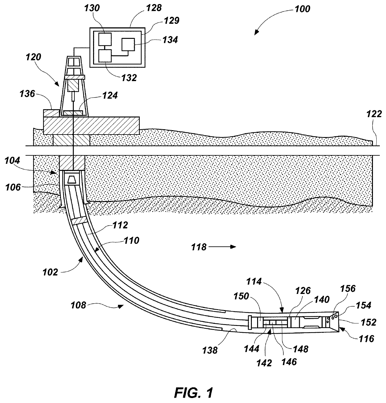
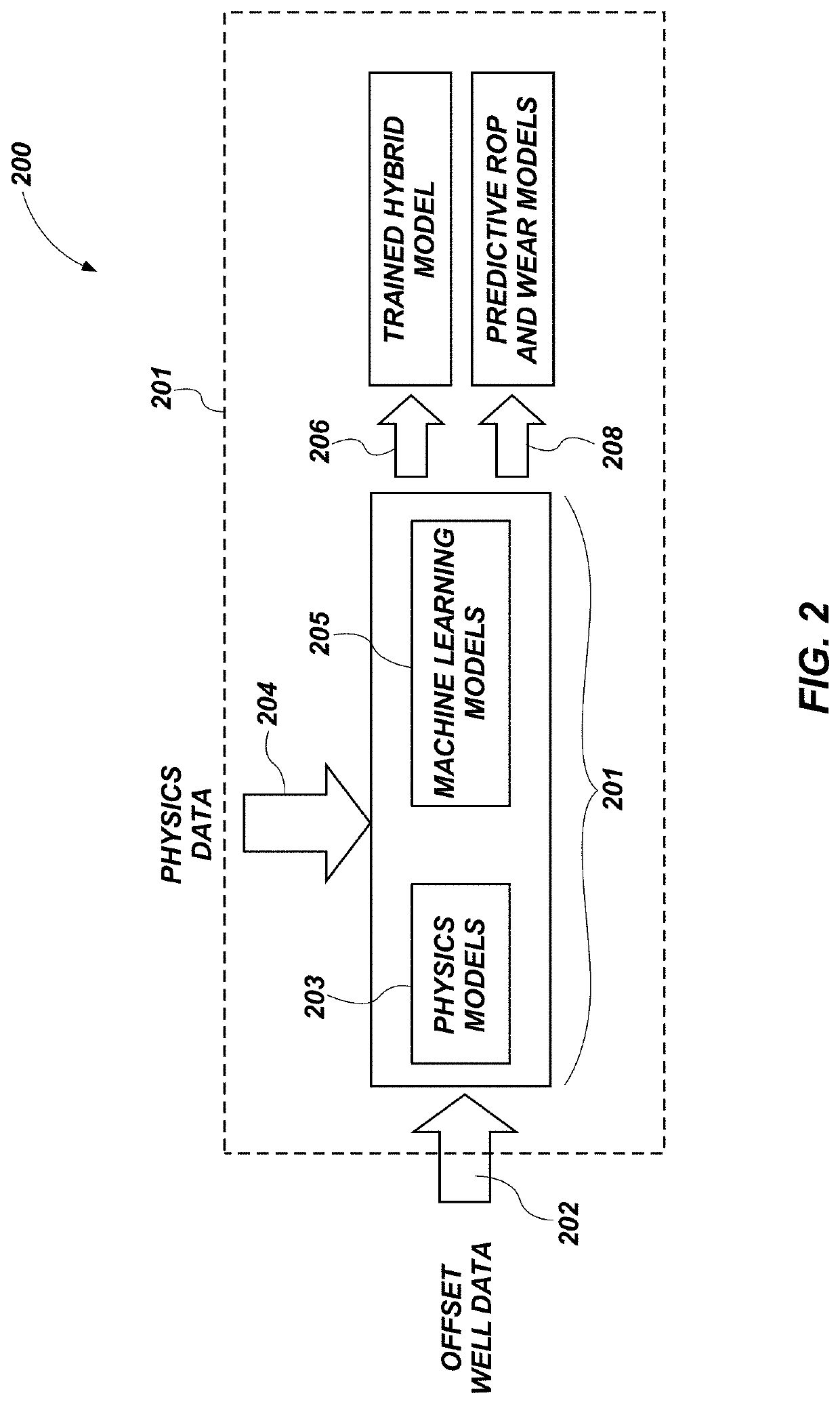
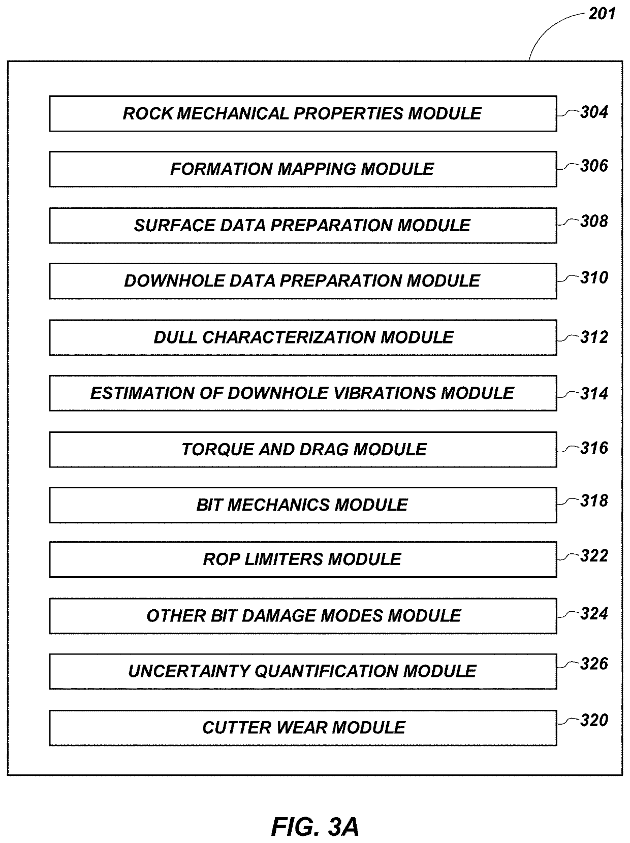
[0020]The illustrations presented herein are not actual views of any drilling system, earth-boring tool monitoring system, or any component thereof, but are merely idealized representations, which are employed to describe embodiments of the present invention.

[0021]As used herein, the terms “bit” and “earth-boring tool” each mean and include earth-boring tools for forming, enlarging, or forming and enlarging a borehole. Non-limiting examples of bits include fixed-cutter (drag) bits, fixed-cutter coring bits, fixed-cutter eccentric bits, fixed-cutter bi-center bits, fixed-cutter reamers, expandable reamers with blades bearing fixed cutters, and hybrid bits including both fixed cutters and rotatable cutting structures (roller cones).

[0022]As used herein, the singular forms following “a,”“an,” and “the” are intended to include the plural forms as well, unless the context clearly indicates otherwise.

[0023]As used herein, the term “may” with respect to a material, structure, feature, or m...


PUM


Abstract

An earth-boring tool system that includes a drilling assembly for drilling a wellbore and a surface control unit. The surface control unit includes a prediction system that is configured to train a hybrid physics and machine-learning model based on input data, provide, via the hybrid model, a predictive model representing a rate of penetration of an earth-boring tool and wear of the earth-boring tool during a planned drilling operation, provide one or more recommendations of drilling parameters based on the predictive model, utilize the one or more recommendations in a drilling operation, receive real-time data from the drilling operation, retrain the hybrid model based on a combination of the input data and the real-time data, and provide, via the retrained model, an updated predictive model of a rate of penetration of an earth-boring tool and wear of the earth-boring tool during a remainder of the planned drilling operation.

Description

TECHNICAL FIELD[0001]This disclosure relates generally to earth-boring tool rate of penetration and wear prediction systems and methods of using such systems.BACKGROUND[0002]Oil wells (wellbores) are usually drilled with a drill string. The drill string includes a tubular member having a drilling assembly that includes a single drill bit at its bottom end. The drilling assembly may also include devices and sensors that provide information pertaining to a variety of parameters relating to the drilling operations (“drilling parameters”), behavior of the drilling assembly (“drilling assembly parameters”) and parameters relating to the formations penetrated by the wellbore (“formation parameters”). A drill bit and / or reamer attached to the bottom end of the drilling assembly is rotated by rotating the drill string from the drilling rig and / or by a drilling motor (also referred to as a “mud motor”) in the bottom hole assembly (“BHA”) to remove formation material to drill the wellbore.[00...

Claims


Application Information

Patent Timeline
IPC IPC(8): E21B44/02E21B21/08E21B45/00E21B47/12E21B49/00
CPCE21B49/003E21B44/02E21B2041/0028E21B47/124E21B45/00E21B21/08E21B44/005E21B2200/22E21B2200/20E21B47/26
Inventor JAIN, JAYESH RAMESHLALBOMIDI, JOHN ABHISHEK RAJHUANG, XU
Owner BAKER HUGHES INC
Why Eureka
Try Eureka