
Log permeability model calibration using reservoir fluid flow measurements

a reservoir fluid and permeability technology, applied in the field of well logging, can solve the problems of inability to accurately predict the permeability of the reservoir, the most difficult to determine or predict the permeability (or fluid conductivity), and the correlation is not always tru

Inactive Publication Date: 2004-02-10
SCHLUMBERGER TECH CORP
View PDF1 Cites 28 Cited by
  • Summary
  • Abstract
  • Description
  • Claims
  • Application Information

AI Technical Summary

Benefits of technology

The patent text describes a method for calibrating a log permeability model using fluid flow measurements and discrete point measurements of permeability. The method involves determining a correlation coefficient for porosity and water saturation, and then using a formation permeability model to estimate the permeability of the formation. The method can provide a consistent and accurate means of calibrating open hole log permeability models that are in agreement with the values obtained from fluid flow analysis or production performance analysis. The method can also be used to calibrate other formation permeability models, such as the Coates and Timur models, by adjusting the coefficients and exponents of the models to minimize the difference between the predicted and measured permeability. Overall, the method provides a reliable and effective means for calibrating log permeability models and evaluating the physical characteristics of reservoir rock from well logs.

Problems solved by technology

Among all formation properties, permeability (or fluid conductivity) is the most difficult to determine or predict.
However, this correlation does not always hold true.
However, these pores and pore channels are too small and the paths available are too restrictive for fluid movement.
Therefore, the permeability of a fine grained sand formation may be quite low.
While formation permeability may be directly determined using core plugs in the laboratory or using a formation fluid tester in a wellbore, these measurements are only practical for providing discrete points of permeability values.
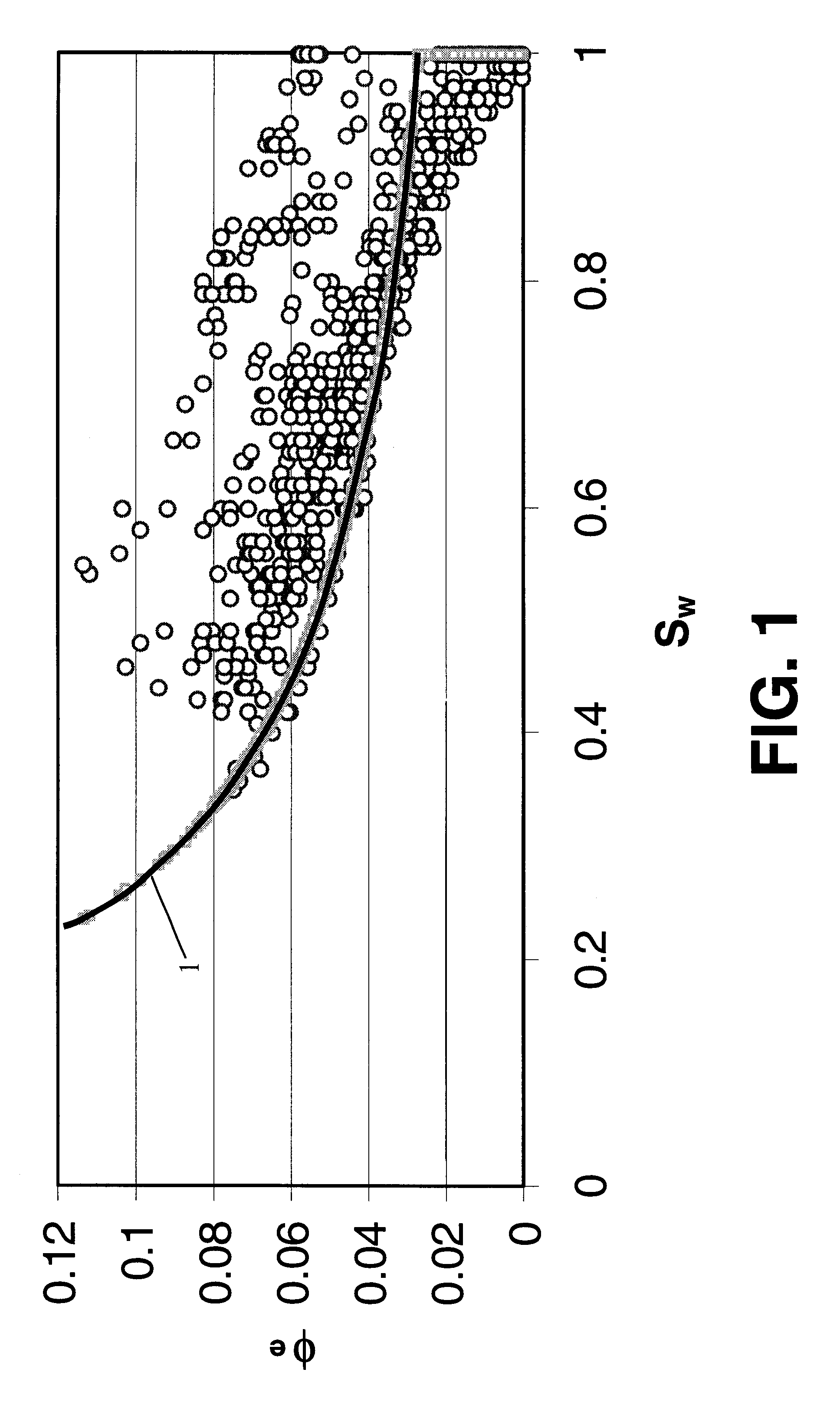
However, porosity derived from well log data is not necessarily effective porosity, and methods for deriving irreducible water saturation often rely on effective porosity.
Furthermore, empirical models developed for certain formation perform poorly when used in other field.

Method used


Image

  • Log permeability model calibration using reservoir fluid flow measurements
  • Log permeability model calibration using reservoir fluid flow measurements
  • Log permeability model calibration using reservoir fluid flow measurements

Examples


Embodiment Construction

FIG. 3 (Well No. 1) shows results obtained with one embodiment of the invention. Production logs were run after all zones were put on production and the results are displayed in the last 2 tracks of the log. Using the production logs and production performance analysis the permeability of the rock associated with each fracture stage was determined and is shown as the shaded area of track 8 on the log (PERMzone). The coefficients for the Coates permeability equation were then calculated.

The inputs for the calculation were the average effective formation permeability to gas for each of the fracture stages (derived from a well production performance analysis), the formation net pay thickness of each fracture stage interval used in the production performance analysis, and the water saturation, total porosity, and effective porosity values determined from the well log analysis. For this example, the B parameter value used in the analysis was the average of all of the zones, and all zones...


PUM


Abstract

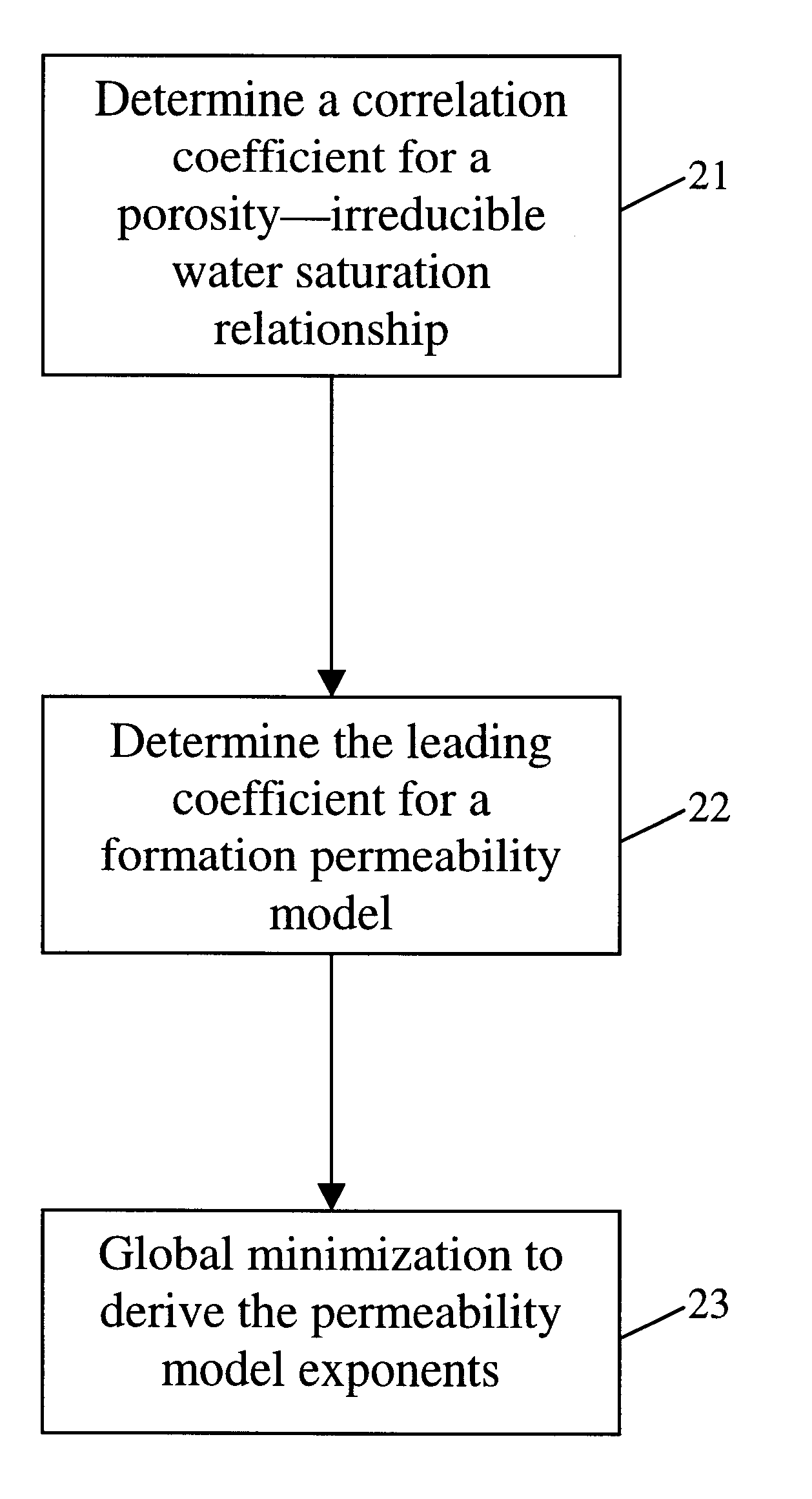
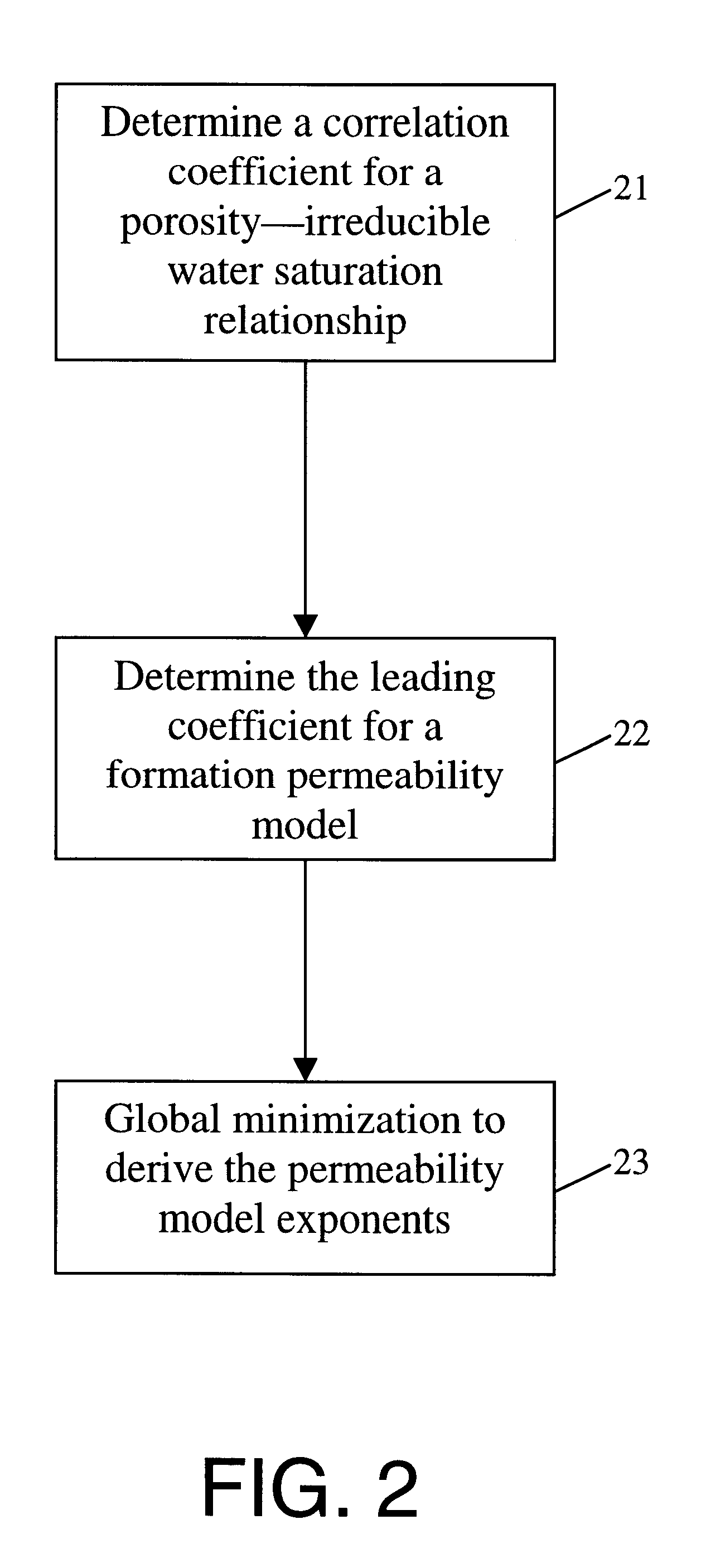
This invention relates to methods for calibrating a formation permeability model with respect to data obtained from fluid flow measurements. A method according to the invention includes determining a correlation coefficient for a porosity-irreducible water saturation relationship; determining a leading coefficient for a formation permeability model; and determining at least one exponent parameter for the formation permeability model by minimizing a basis function that represents a difference between a formation permeability estimate derived from the formation permeability model and a formation permeability estimate derived from the fluid flow measurements.

Description

BACKGROUND OF INVENTION1. Field of the InventionThe present invention relates to the field of well logging. More specifically, the present invention relates to methods for formation permeability estimation.2. Background ArtReservoir characterization is important for oil and gas production. Knowledge of formation properties is essential for effective management of the production process. Among all formation properties, permeability (or fluid conductivity) is the most difficult to determine or predict. Permeability is a measure of the ease with which a formation permits a fluid to flow through it.To be permeable, a rock must have interconnected porosity (pores, vugs, capillaries, fissures or fractures). Greater porosity usually correlates with greater permeability. However, this correlation does not always hold true. For example, a formation of fine-grained sands may have highly interconnected pores. However, these pores and pore channels are too small and the paths available are too ...

Claims


Application Information

Patent Timeline
Patent Type & Authority Patents(United States)
IPC IPC(8): G01V11/00
CPCG01V11/00E21B49/00
Inventor POE, BOBBY D.BUTSCH, ROBERT J.
Owner SCHLUMBERGER TECH CORP
Learn More