

Downhole sample rate system
- Summary
- Abstract
- Description
- Claims
- Application Information
AI Technical Summary
Problems solved by technology
Method used
Image

Examples
Embodiment Construction
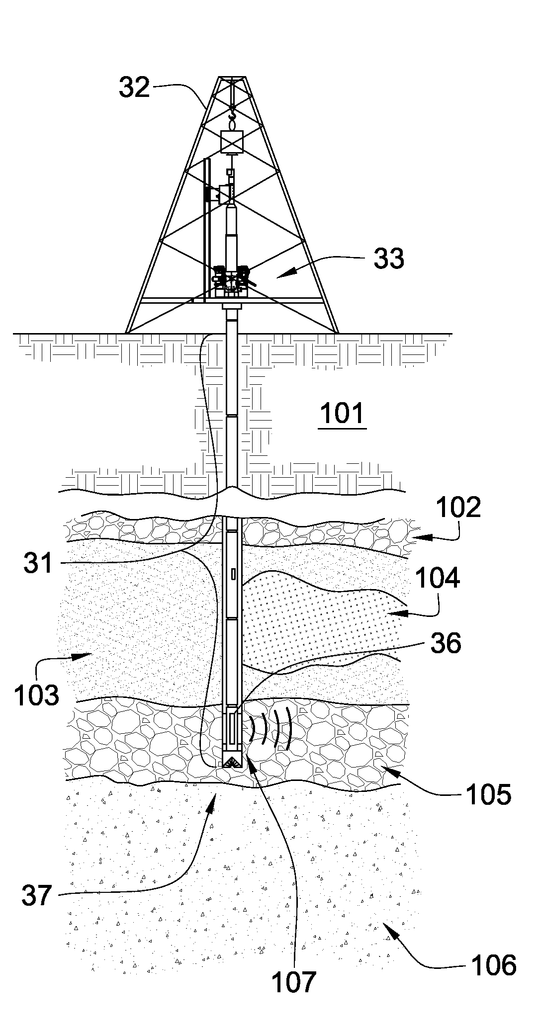
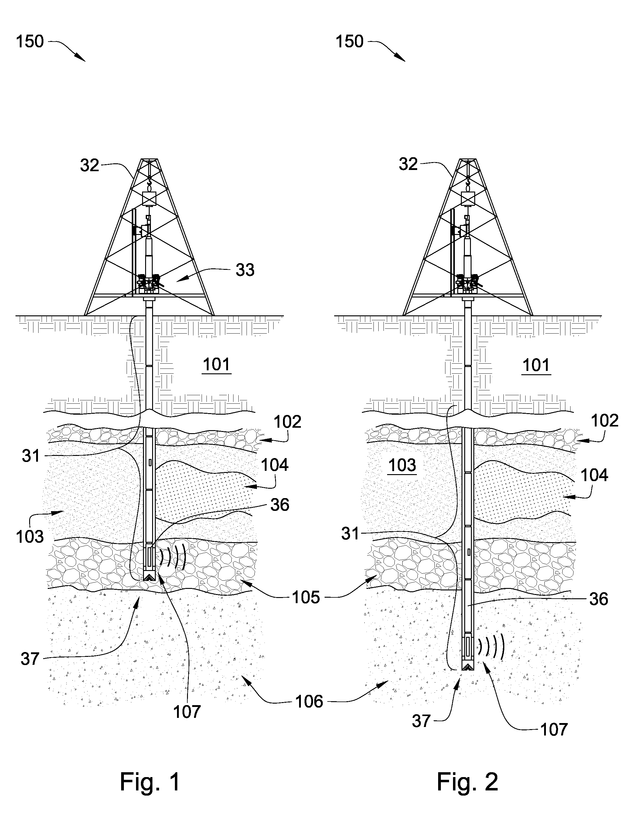
[0033]Referring now to FIGS. 1 and 2, a downhole tool string 31 is suspended from a derrick 32 in a drilling rig 150. The tool string 31 may comprise one or more downhole components 36, linked together in a tool string 31 and in communication with surface equipment 33 through a downhole network or the tool string may comprise another telemetry system such as mud pulse or electromagnetic waves. The tool string 31 is depicted in a vertical drilled hole but it may be at any angle including horizontal. In FIGS. 1 and 2 a plurality of formation strata 101, 102, 103, 104, 105, and 106 are shown. The tool string 31 in FIG. 1 extends into formation strata 101, 102, 103, 104, and 105, but not into formation stratum 106. In FIG. 2 the tool string 31 extends into all formation strata 101-106.
[0034]The tool string 31 or surface equipment 33 may comprise an energy source or multiple energy sources. The energy source may transmit electrical current to one or more downhole components 36 on the bot...
PUM
 Abstract
Description
Claims
Application Information