
Automatic cooling motor construction having driver connected on the back

A drive and motor technology, applied in the field of back-connected drives and motors, can solve the problems of unable to discharge hot air from the drive, poor heat dissipation, and space occupied by external solutions

Active Publication Date: 2012-03-21
DELTA ELECTRONICS INC
View PDF0 Cites 0 Cited by
  • Summary
  • Abstract
  • Description
  • Claims
  • Application Information

AI Technical Summary

Problems solved by technology

[0003] However, the technical content disclosed in the prior art to solve the heat dissipation problem of the motor driver is to solve the heat dissipation problem by adding structures such as heat dissipation fins, which leads to defects such as increased volume and weight of the overall motor device, and the method The hot air inside the drive cannot be effectively discharged, and its heat dissipation effect is not good
However, if the external fan uses airflow to provide heat dissipation for the motor driver, it is necessary to add a power supply configuration for the external fan, and the external solution also takes up a lot of space, which is obviously inconvenient

Method used


Image

  • Automatic cooling motor construction having driver connected on the back
  • Automatic cooling motor construction having driver connected on the back
  • Automatic cooling motor construction having driver connected on the back

Examples


Embodiment Construction

[0026] In order for those skilled in the art to further understand the features and technical content of the present invention, please refer to the following detailed description and accompanying drawings of the present invention. The accompanying drawings are only for reference and description, and are not intended to limit the present invention.

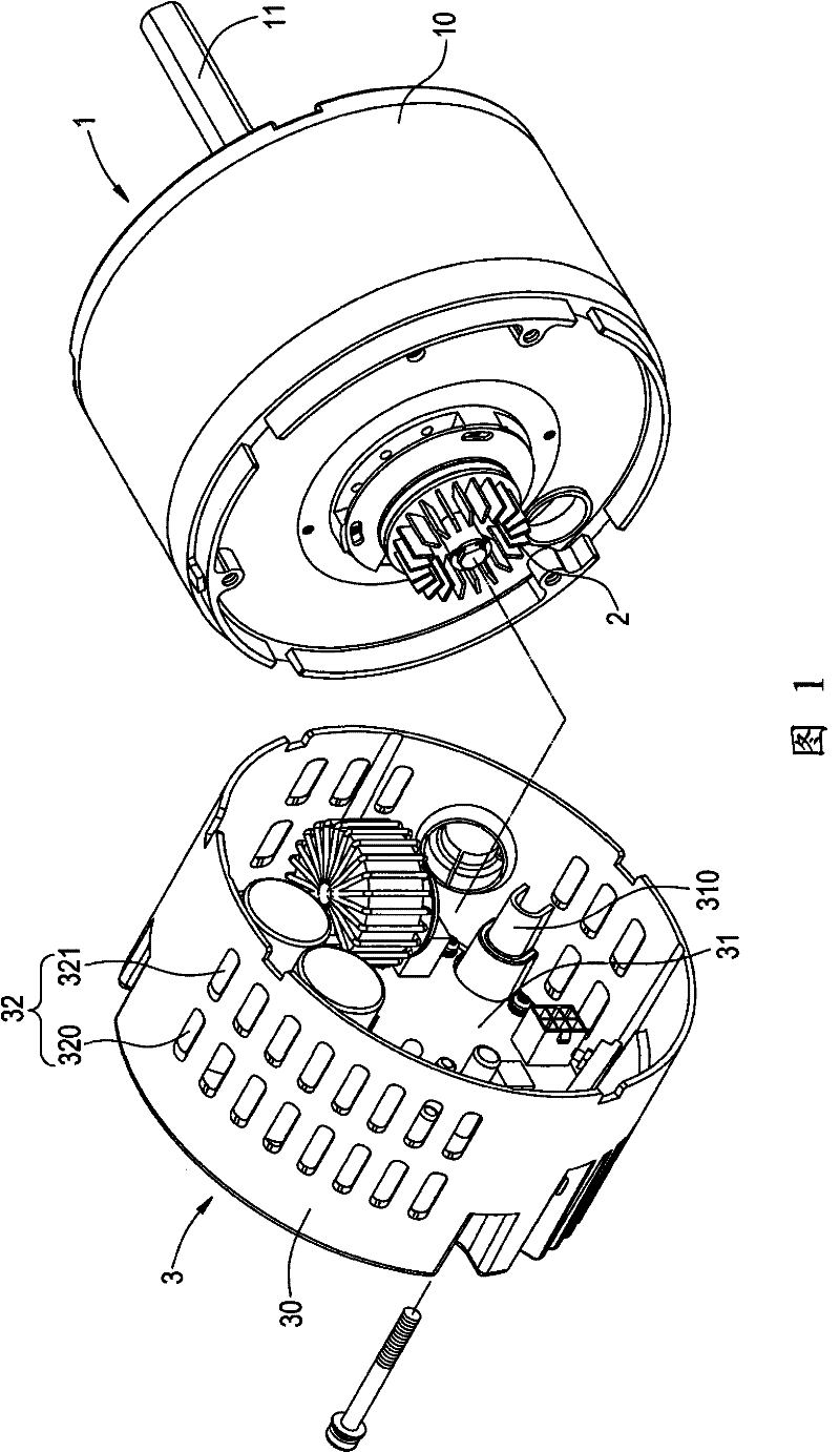
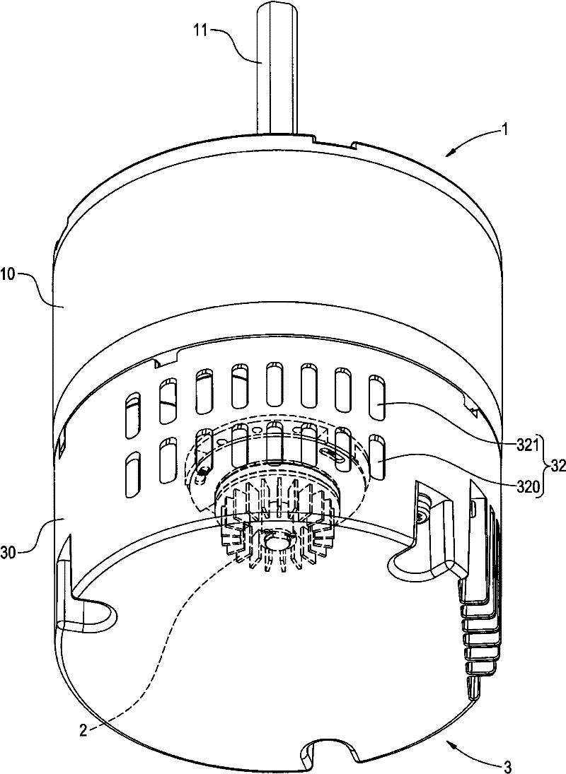
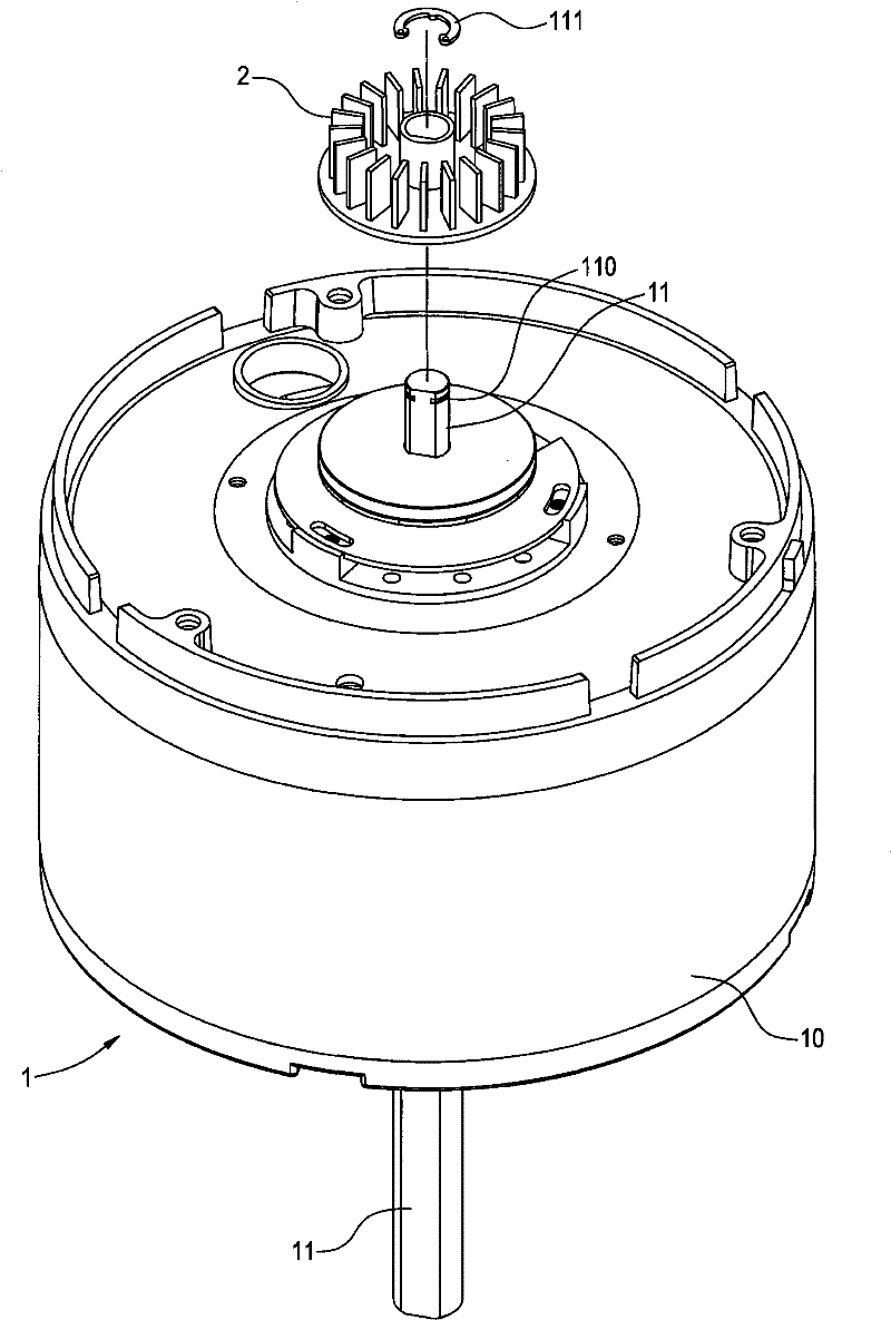
[0027] figure 1 with figure 2 Respectively, the three-dimensional exploded view and the combined schematic view of the present invention. The present invention provides a motor structure with an automatic heat dissipation type back-connected driver, including a motor 1, a centrifugal fan 2, and a driver 3; wherein: the motor 1 is a rotary power device with a motor body 10, and the inside of the motor body 10 is mainly through a stator and a rotor and other components are used to drive the rotation of the rotating shaft 11 pivoted on the motor body 10 . The rotating shaft 11 protrudes at the front and rear ends of the motor body ...


PUM


Abstract

Disclosed is a motor structure of an automatic heat-radiating backing driver, comprising a motor, a centrifugal fan and a driver; wherein, the motor is provided with a motor body and a rotating shaft which is pivoted on the motor body and protrudes from the front end and the rear end of the motor body, the centrifugal fan is disposed at the tail end of the rotating shaft and is driven by the motor, in addition, the driver is equipped with a shell nested at the outside of the centrifugal fan on the motor body, a plurality of air holes are arranged on the side wall face of the shell, and the air holes include a plurality of air inlet holes far away from the motor body and a plurality of air outlet holes close to the motor body; thereby, the rotating shaft of the motor is rotated and the centrifugal fan is utilized to disperse the heat in the motor driver.

Description

technical field [0001] The invention relates to a rotary power device, in particular to a back-connected drive for driving a centrifugal fan through the rotation of the motor, and a motor for dissipating heat from the drive by air flow. Background technique [0002] Existing devices such as motor drivers or driving devices generally use a heat dissipation structure with added heat dissipation fins to achieve the purpose of heat dissipation. [0003] However, the technical content disclosed in the prior art to solve the heat dissipation problem of the motor driver is to solve the heat dissipation problem by adding structures such as heat dissipation fins, which leads to defects such as increased volume and weight of the overall motor device, and the method The hot air inside the driver cannot be effectively discharged, and its heat dissipation effect is not good. However, if an external fan is used to provide heat dissipation for the motor driver with airflow, it is necessar...

Claims


Application Information

Patent Timeline
Patent Type & Authority Patents(China)
IPC IPC(8): H02K9/06H02K5/20H02K11/00H02K11/33
Inventor 邢雷钟林鸿志
Owner DELTA ELECTRONICS INC
Learn More