
Foldable desk

A foldable table technology, applied in foldable table, detachable table, table, etc., can solve the problems of high cost, failure to prevent collision sound, expensive buffer, etc., to improve strength, expand lower body space, Smooth turning effect

Inactive Publication Date: 2012-07-04
ITOKI CORP
View PDF6 Cites 0 Cited by
  • Summary
  • Abstract
  • Description
  • Claims
  • Application Information

AI Technical Summary

Problems solved by technology

In order to prevent this problem, there are also structures that implement countermeasures such as installing soft cushioning materials on the back plate or the leg body, but the generation of impact noise due to impact or vibration of the back plate cannot be completely suppressed.
In addition, there is also a structure in which the lateral width of the above-mentioned back plate is set to be narrower than that between the left and right leg bodies. In this case, although the back plate does not collide with the leg bodies, the link member may not collide with the back plate or the leg bodies. Collision still cannot prevent the generation of collision sound, and when multiple folding tables are arranged side by side, there will be a large gap between the adjacent backboards, resulting in the deterioration of the original function of the backboards to block the line of sight
In addition, in the folding table described in Patent Document 6, since an oil buffer is provided on the rotation shaft of the top plate, there is resistance to the rotation of the top plate in one side direction, so that the sudden lifting of the top plate and the back plate and the legs cannot be prevented. body collision, and because the buffer itself is expensive, the cost becomes high

Method used


Image

  • Foldable desk
  • Foldable desk
  • Foldable desk

Examples


Embodiment Construction

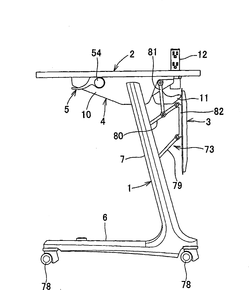
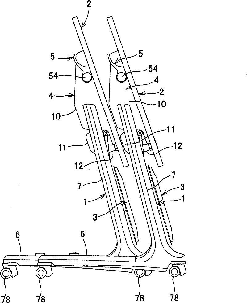
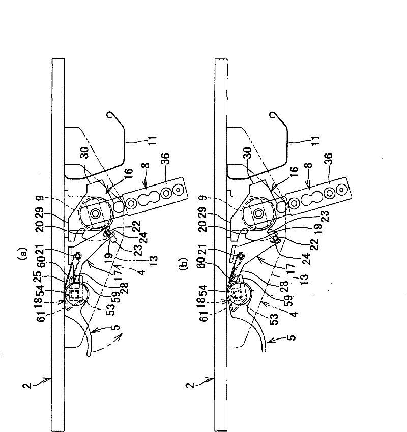
[0087] Next, the present invention will be described in detail based on the embodiments shown in the drawings. figure 1 It is an overall side view of the use posture of the folding table of this embodiment; figure 2 is a side view of the storage state in the folded posture; image 3 is a partial side view showing the rotation mechanism part and the locking mechanism part; Figure 4 to Figure 20 Indicates the details of each part. The number 1 in the figure represents the leg body, 2 represents the top board, 4 represents the back board, and 5 represents the operating rod.

[0088] In the folding table of the present embodiment, the upper ends of the left and right leg bodies 1 and 1 are rotatably connected up and down to both sides of the lower surface of the top plate 2, and the top plate 2 can be changed into a substantially horizontal use posture (refer to figure 1 ) and the folded posture with the front of the top panel 2 turned upward (refer to figure 2 ), and conne...


PUM


Abstract

The invention provides a folding-type desk, on an upper end of left and right supporters, brackets, which are connectively mounted on two sides of a lower surface of a top plate in a manner of rotating upwards and downwards, maintains the top plate in a horizontal using gesture and a folding gesture, wherein lower limb space can be expanded, intensity of the supporters are increased, and rotational operation of the top plate can be smoothly performed, in addition, when the top plate changes the using gesture to the folding gesture, the brake can be applied to the top plate to prevent rapid rising of the top plate. A circular bearing hole (31) is formed on a side plate at outside of the bracket, and an opening (32) is formed on a side plate at inside such that the end of a connection pipe (9) is located within the bracket from the opening to form a shaft section (38) on a horizontal section (37), the shaft section (38) is rotatably tabled on a sliding ring (34) mounted on the bearing hole and enables the front end to be located within the bracket, the horizontal section and the connection pipe of the supporter connection component are interconnected in a non-rotating manner within the bracket.

Description

technical field [0001] The present invention relates to a folding table, and more specifically relates to a top plate that can maintain a substantially horizontal use posture and a folded posture that can be turned upward to stand upright, and a backboard provided under the rear portion of the top board moves in conjunction with the movement of the top board. Folding table. Background technique [0002] Conventionally, various folding tables have been provided in which the upper ends of the left and right legs are vertically rotatably connected to both sides of the lower surface of the top plate, and the top plate is fixed in a substantially horizontal use posture and an upwardly folded folding posture. It is also known to connect a bracket mounted on both sides of the top plate to the upper end of the leg body so as to be rotatable up and down, and to provide a locking mechanism in the bracket to maintain the top plate in the use position and the folded position. [0003] ...

Claims


Application Information

Patent Timeline
Patent Type & Authority Patents(China)
IPC IPC(8): A47B3/083
Inventor 前川尚幸富本浩一郎
Owner ITOKI CORP
Learn More