Inductance coupling plasma apparatus

A plasma and inductive coupling technology, applied in the direction of plasma, circuits, electrical components, etc., can solve the problems of lower product yield, poor etching uniformity, etc., and achieve the effect of improving quality

Active Publication Date: 2014-09-24
BEIJING NAURA MICROELECTRONICS EQUIP CO LTD
View PDF5 Cites 0 Cited by
  • Summary
  • Abstract
  • Description
  • Claims
  • Application Information

AI Technical Summary

Problems solved by technology

[0004] like figure 2 As shown, the inductively coupled coil 4 in the prior art is centrosymmetric and is fixed on the side wall or upper cover of the reaction chamber 3. The centrosymmetrically coupled inductively coupled coil 4 can generate centrosymmetric plasma, but, because of the mechanical Due to structural limitations, the pumping method of the reaction chamber of most etching machines is not centrosymmetric, which causes the original centrosymmetric plasma to become a non-centrosymmetric plasma under the influence of the asymmetric pumping method , so that the uniformity of etching in the circumferential direction is deteriorated and the product yield is reduced

Method used


Image

  • Inductance coupling plasma apparatus
  • Inductance coupling plasma apparatus
  • Inductance coupling plasma apparatus

Examples


specific Embodiment 2

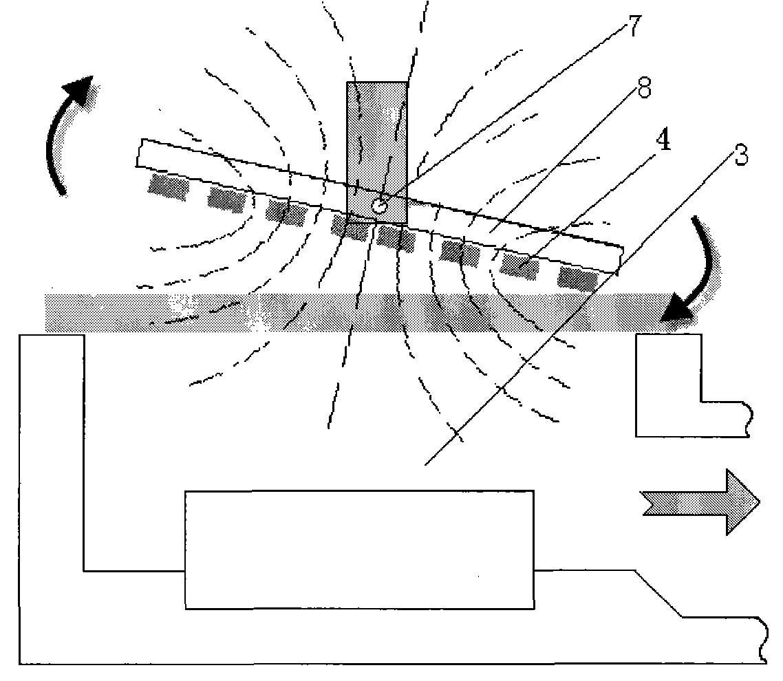
[0018] In the second specific embodiment, the connecting device includes two horizontal axes, and the two horizontal axes are perpendicular to each other, and the inductively coupled coil 4 can rotate around any one of the horizontal axes. Two mutually perpendicular horizontal axes constitute a directional connection device, so that the inductively coupled coil 4 can be inclined in any direction relative to the reaction chamber 3 .

specific Embodiment 3

[0019] In the third specific embodiment, the connecting device further includes a vertical axis, and the inductively coupled coil can rotate around the vertical axis and the horizontal axis. A universal connection device can also be formed so that the inductively coupled coil 4 can be inclined in any direction relative to the reaction chamber 3 .

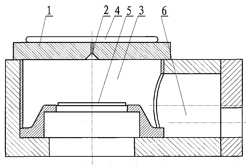
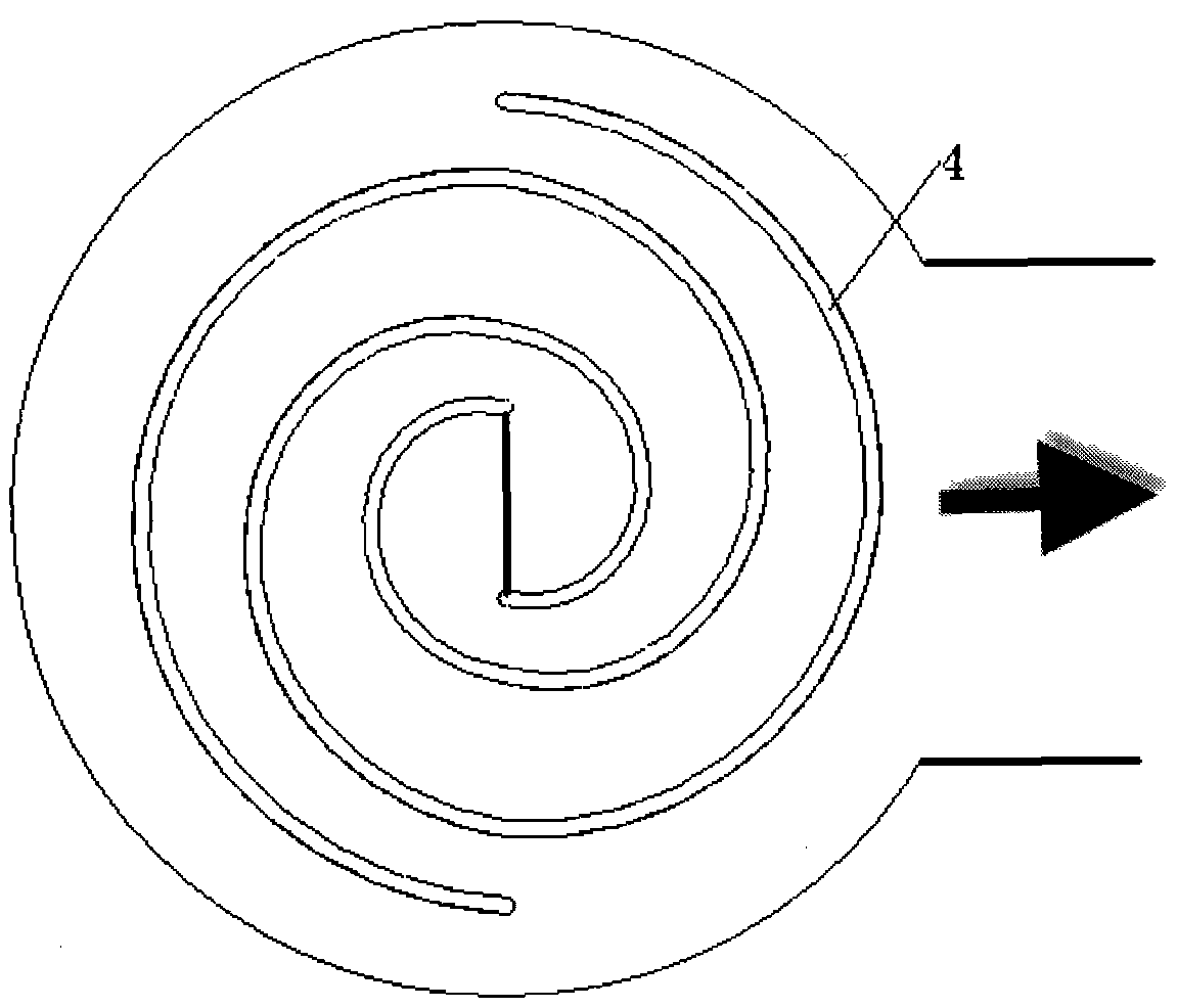
[0020] In general, the plane of the inductively coupled coil 4 is parallel to the plane of the quartz cover above the reaction chamber 3 and the plane of the wafer. When the mechanical structure of the reaction chamber 3 and the way of pumping air are completely symmetrical, the coil placed horizontally has a good effect. , However, when the mechanical structure of the reaction chamber 3 is asymmetric, the inherent central symmetry of the coil is destroyed, resulting in an eccentric phenomenon in the etching rate distribution.

[0021] The present invention can properly adjust the inclination angle between the coil and the quartz co...


PUM


Abstract

The invention discloses a inductance coupling plasma device comprising machine body, reaction chamber. A inductance coupling coil is provided at upper of reaction chamber, and connected with machine body through connecting device; the connecting device comprises horizontal axis; inductance coupling coil can rotates around horizontal axis, which can make inductance coupling coil incline a certain angle corresponding to reaction chamber, compensate plasma distribution symmetry breaking arising from unsymmetrical structure such as air suction mode, obtains more uniform plasma and better process result. The invention is used for semiconductor chip processing equipment and other similar equipment.

Description

technical field [0001] The invention relates to semiconductor wafer processing equipment, in particular to an inductively coupled plasma device. Background technique [0002] At present, with the rapid development of electronic technology, people have higher and higher requirements for the integration of integrated circuits, which requires enterprises that produce integrated circuits to continuously improve the processing capacity of semiconductor wafers. Plasma devices are widely used in manufacturing processes for manufacturing IC (Integrated Circuit) or MEMS (Micro Electro Mechanical System) devices. Among them, ICP (inductively coupled plasma device) is widely used in etching and other processes. Under low pressure, the reactive gas is excited by radio frequency power to generate ionization to form a plasma. The plasma contains a large number of active particles such as electrons, ions, excited atoms, molecules and free radicals. These active reactive groups and the eng...

Claims


Application Information

Patent Timeline
Patent Type & Authority Patents(China)
IPC IPC(8): H01L21/00H05H1/34
Inventor 申浩南
Owner BEIJING NAURA MICROELECTRONICS EQUIP CO LTD
Why Eureka
Try Eureka