Device for reducing influence of birefringent chromatic dispersion on polarization coupling measurement of polarization maintaining optical fiber

A polarization-maintaining fiber, coupling measurement technology, applied in the direction of testing optical performance, etc., can solve the problems of reducing the spatial resolution of polarization mode coupling, envelope broadening and interference peak drop, resolution and coupling strength detection sensitivity decrease, etc.

Active Publication Date: 2013-06-05
HARBIN ENG UNIV
View PDF4 Cites 1 Cited by
  • Summary
  • Abstract
  • Description
  • Claims
  • Application Information

AI Technical Summary

Problems solved by technology

Research shows: (Tianhua Xu, Wencai Jing, Hongxia Zhang, et.al.Influence of birefringence dispersion on a distributed stress sensor using birefringent optical fiber, Optical Fiber Technology, Volume 15, Issue1, January 2009, Pages 83-89, and Feng Tang, Xiang-zhao Wang, Yimo Zhang, Wencai Jing, Influence of birefringence dispersion on distributed measurement of polarization coupling in birefringent fibers, Opt.Eng., Vol.46, 075006(2007)) The dual effect of network broadening and interference peak reduction reduces the spatial resolution of polarization mode coupling and reduces the detection sensitivity of coupling strength
And the influence of birefringence dispersion is dynamic, and it is related to the distance from the coupling point to the starting point of the fiber. As the distance increases, the spatial resolution of the coupling point test and the detection sensitivity of the coupling strength decrease.
With a length of 1000 meters and a birefringence of 6×10 -4 For example, take a polarization-maintaining fiber with a dispersion coefficient of 0.01ps / (km nm) as an example, and use a light source with a half-spectrum width of 50nm for interrogation. The original coherence increased from 34 μm to 0.94 mm in length, so that the spatial resolution of the polarization coupling of the polarization-maintaining fiber dropped from 5.6 cm to 1.6 meters, seriously affecting the measurement accuracy

Method used


Image

  • Device for reducing influence of birefringent chromatic dispersion on polarization coupling measurement of polarization maintaining optical fiber
  • Device for reducing influence of birefringent chromatic dispersion on polarization coupling measurement of polarization maintaining optical fiber
  • Device for reducing influence of birefringent chromatic dispersion on polarization coupling measurement of polarization maintaining optical fiber

Examples


specific Embodiment approach 1

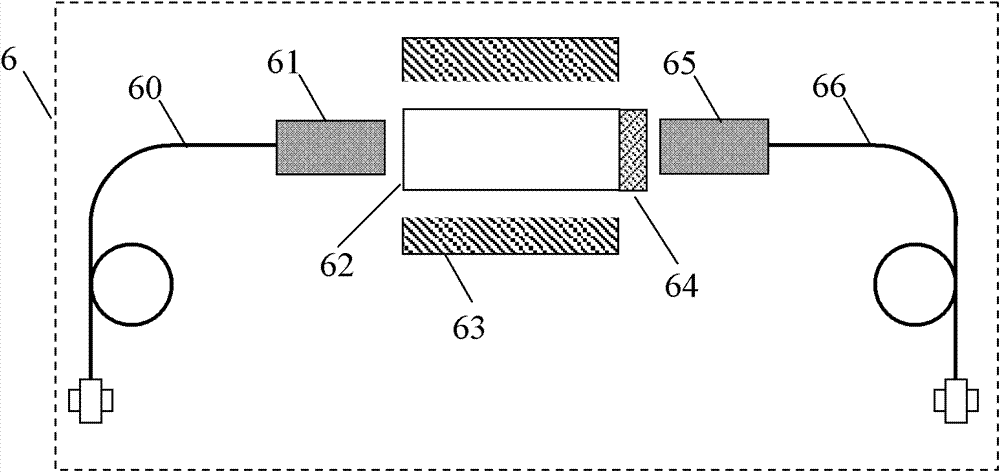
[0051] Such as image 3 As shown, the semi-reflective and semi-transparent polarization rotator 6 can be realized by the optical rotation effect of a magnetic field. Semi-reflective polarization rotator 6 is composed of input and output polarization-maintaining fiber 60, input and output polarization-maintaining fiber collimator 61, 45° rotator crystal 62, permanent magnet ring 63, semi-reflective half mirror 64, working wavelengths are all selected It is 1550nm. The light beam is input by the optical fiber 60 and turned into parallel light by the collimator 61. After passing through the rotatory crystal 62 placed in the magnetic field (generated by the magnetic ring 63), the polarization state of the light beam is rotated by 45°, and the light beam is input through the half mirror 64 After being split into two beams, the transmitted beam is focused by the exit collimator 65 and enters the exit fiber 66; the reflected beam passes through the rotator crystal 62 again, the polari...

specific Embodiment approach 2

[0053] Such as Figure 5 As shown, the semi-reflective and semi-transparent polarization rotator 6 can also be realized by the optical rotation function of the half-wave plate. The semi-reflective and semi-transparent polarization rotator 6 is composed of an input and output polarization maintaining fiber 60, an input and output polarization maintaining fiber collimator 61, a half wave plate 67, and a half mirror 64, and the working wavelength is selected to be 1550 nm. The light beam is input by the optical fiber 60 and turned into parallel light by the collimator 61. After the polarization axis is placed on the 22.5° half-wave plate 67, the polarization state of the light beam is rotated by 45°, and the input light beam is split into two beams through the half mirror 64 After the transmitted light beam is focused by the exit collimator 65, it enters the exit fiber 66; the reflected light beam is again half-wave plate 67, the polarization state is rotated by 90°, is focused by...


PUM


Abstract

The invention provides a device for reducing an influence of birefringent chromatic dispersion on polarization coupling measurement of a polarization maintaining optical fiber. The device comprises a broadband light source (1), the polarization maintaining optical fiber to be measured (3), a polarization coupling detection device (4), a first connection optical fiber (53), a second connection optical fiber (54), a three-port optical circulator (2), a semi-reflective and semi-transparent light beam polarization light rotator (6), a light rotator (7), a first rotary connector (51) and a second rotary connector (52), wherein the semi-reflective and semi-transparent light beam polarization light rotator divides broadband light into two uniform light beams which simultaneously pass through theoptical fiber to be measured from the clockwise direction and the anticlockwise direction; and by using the same polarization coupling detection device, two pieces of polarization coupling measurement data of which the scanning positions are symmetric with each other are acquired at the same time. The device has extremely important practical value for parameter measurement and performance evaluation of an optic fiber gyroscope sensitive ring and can be widely applied to distributed polarization optical fiber sensing systems.

Description

Technical field [0001] The invention relates to a fiber polarization coupling measurement device, in particular to a device that reduces the influence of birefringence dispersion on the polarization coupling measurement of a polarization maintaining fiber. Background technique [0002] Polarization maintaining fiber is a special function of fiber waveguide, which refers to the fiber that can always maintain the original polarization state during transmission in the fiber when a polarization mode is excited. In the interferometric optical fiber sensing technology, the use of polarization-maintaining fiber can overcome the influence of the external environment on the polarization state of the light wave transmitted in the fiber, and suppress the polarization fading phenomenon caused by interferometric measurement. Especially in some high-precision fiber optic sensors, such as fiber optic gyroscopes, fiber optic hydrophones and so on. [0003] The main parameters for evaluating the p...

Claims


Application Information

Patent Timeline
Patent Type & Authority Patents(China)
IPC IPC(8): G01M11/02
Inventor 杨军苑立波
Owner HARBIN ENG UNIV
Why Eureka
Try Eureka