Method and device for directly coupling hollow-core photonic band gap optical fiber ring and integrated optical chip based on composite light guide mechanism

A technology of photonic bandgap and integrated optics, which is applied in the field of optical fiber device manufacturing, can solve problems such as hindering the development of hollow-core photonic bandgap fiber optic gyroscopes, destroying the reciprocity and symmetry of optical paths, and large losses in pigtail welding methods. Unreliability, eliminate the influence of optical path reciprocity and symmetry, and improve the effect of environmental adaptability

Active Publication Date: 2020-03-06
BEIHANG UNIV
View PDF7 Cites 3 Cited by
  • Summary
  • Abstract
  • Description
  • Claims
  • Application Information

AI Technical Summary

Problems solved by technology

[0005] The present invention aims at the large loss and strong back reflection of the current hollow-core photonic bandgap optical fiber ring and the integrated optical chip pigtail fusion method, and the small non-reciprocal phase shift generated by the fusion point will destroy the reciprocity and symmetry of the optical path, which is harmful to the gyroscope. The accuracy has an important impact, which seriously hinders the development of the hollow-core photonic bandgap fiber optic gyroscope. A method and device for direct coupling between the hollow-core photonic bandgap fiber ring and the integrated optical chip based on the composite light guiding mechanism are proposed.

Method used


Image

  • Method and device for directly coupling hollow-core photonic band gap optical fiber ring and integrated optical chip based on composite light guide mechanism
  • Method and device for directly coupling hollow-core photonic band gap optical fiber ring and integrated optical chip based on composite light guide mechanism
  • Method and device for directly coupling hollow-core photonic band gap optical fiber ring and integrated optical chip based on composite light guide mechanism

Examples


Embodiment Construction

[0027] In order to facilitate those of ordinary skill in the art to understand and implement the present invention, the present invention will be further described in detail and in-depth below in conjunction with the accompanying drawings.

[0028] First, the direct coupling device between the hollow-core photonic bandgap fiber ring and the integrated optical chip based on the composite light guiding mechanism realized by the present invention is described.

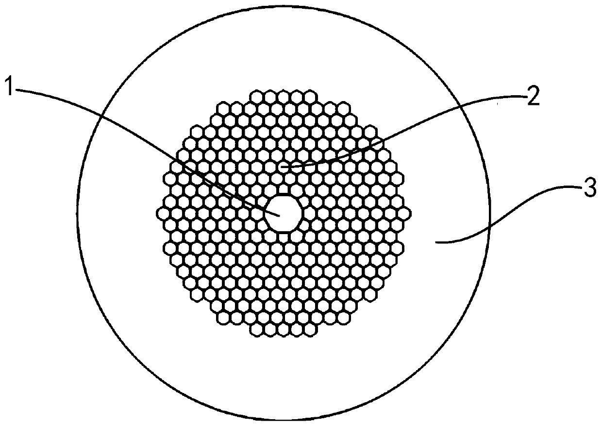
[0029] Such as figure 1 As shown, the end face structure of the hollow-core photonic bandgap fiber used in the present invention includes a large core air hole 1 , a cladding small air hole 2 and a cladding quartz layer 3 .

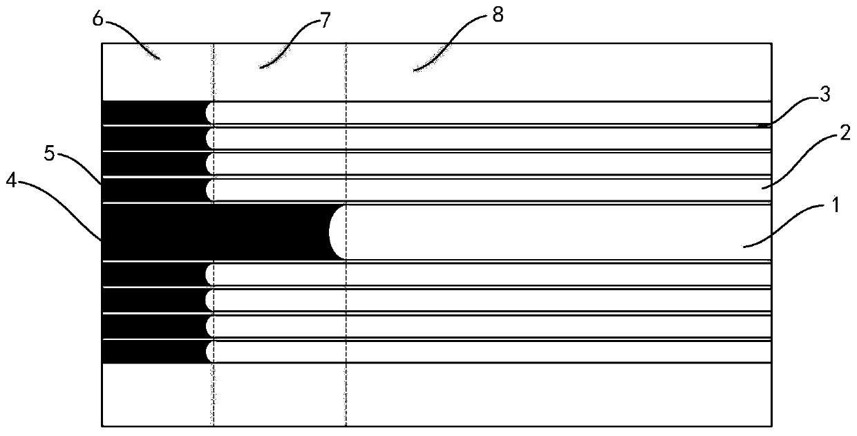
[0030] Such as figure 2 As shown, the present invention injects high-refractive-index optical glue 4 into the large core air hole 1 on the end face of the hollow-core photonic bandgap fiber, and injects low-refractive-index optical glue 5 into the cladding small air hole 2 . Mark the part of the h...


PUM


Abstract

The invention provides a method and a device for directly coupling a hollow-core photonic band gap optical fiber ring and an integrated optical chip based on a composite light guide mechanism, and belongs to the technical field of optical fiber device manufacturing. The method and the device aim at the problem of coupling of the hollow-core photonic band gap optical fiber ring which restricts theperformance of a hollow-core photonic band gap optical fiber gyroscope. The device comprises the hollow-core photonic band gap optical fiber ring with the composite light guide mechanism, a clamp andthe integrated optical chip. The method comprises the following steps of: 1, acquiring a flat end face of the hollow-core photonic band gap optical fiber ring; 2, injecting high-refractive-index optical cement and low-refractive-index optical cement into a fiber core large air hole and a cladding small air hole of the end face correspondingly; and 3, directly coupling the hollow-core photonic bandgap optical fiber ring with the composite light guide mechanism and the integrated optical chip. According to the method and the device, welding is not required, the influence of welding points on the reciprocity of an optical path is eliminated, and the low-loss, low-back reflection and high-reliability direct coupling of the hollow-core photonic band gap optical fiber ring and the integrated optical chip is realized by selectively filling proper high-refractive-index optical cement and low-refractive-index optical cement.

Description

technical field [0001] The invention belongs to the technical field of optical fiber device manufacturing, and in particular relates to a direct coupling method and device for a hollow-core photonic bandgap optical fiber ring and an integrated optical chip based on a composite light guiding mechanism. Background technique [0002] The hollow-core photonic bandgap fiber is based on the photonic bandgap effect to guide light. Its cladding is a periodic arrangement of glass tubes, forming a two-dimensional photonic crystal with a periodic distribution of high and low refractive indices, generating a photonic bandgap, and the frequency is within the photonic bandgap. Light cannot be transmitted in it, so it cannot be transmitted in the cladding. The large air hole in the fiber core causes defects in the two-dimensional photonic crystal, and the photonic band gap produces a defect state with an extremely narrow frequency. The light energy of this specific frequency is transmitted...

Claims


Application Information

Patent Timeline
Patent Type & Authority Applications(China)
IPC IPC(8): G02B6/26G02B6/25
CPCG02B6/25G02B6/262
Inventor 徐小斌何程宋凝芳高福宇刘嘉琪王晓阳朱云浩
Owner BEIHANG UNIV
Why Eureka
Try Eureka