Supercharge Your Innovation With Domain-Expert AI Agents!

Fuel cell

A fuel cell and electrode assembly technology, which is applied to fuel cells, fuel cell groups, and fuel cell components, etc., and can solve problems such as failures and mutual interference.

Inactive Publication Date: 2009-02-18
TOYOTA JIDOSHA KK
View PDF1 Cites 5 Cited by
  • Summary
  • Abstract
  • Description
  • Claims
  • Application Information

AI Technical Summary

Problems solved by technology

But with this structure, the protrusions formed on the gaskets arranged successively with the separator inserted therebetween interfere with each other.
As a result, a failure occurs

Method used


Image

  • Fuel cell
  • Fuel cell
  • Fuel cell

Examples


Embodiment Construction

[0017] Hereinafter, exemplary embodiments of the present invention will be described in detail with reference to the accompanying drawings.

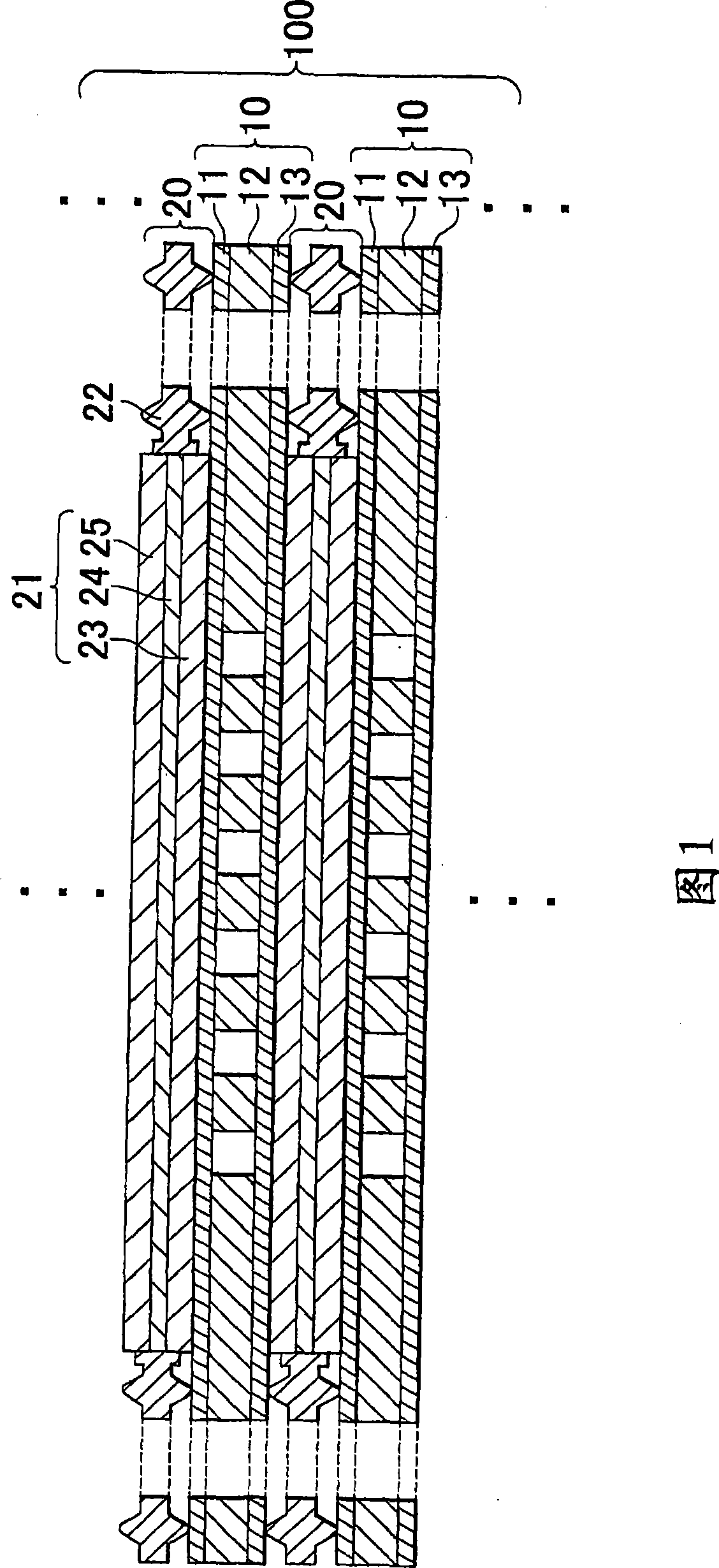
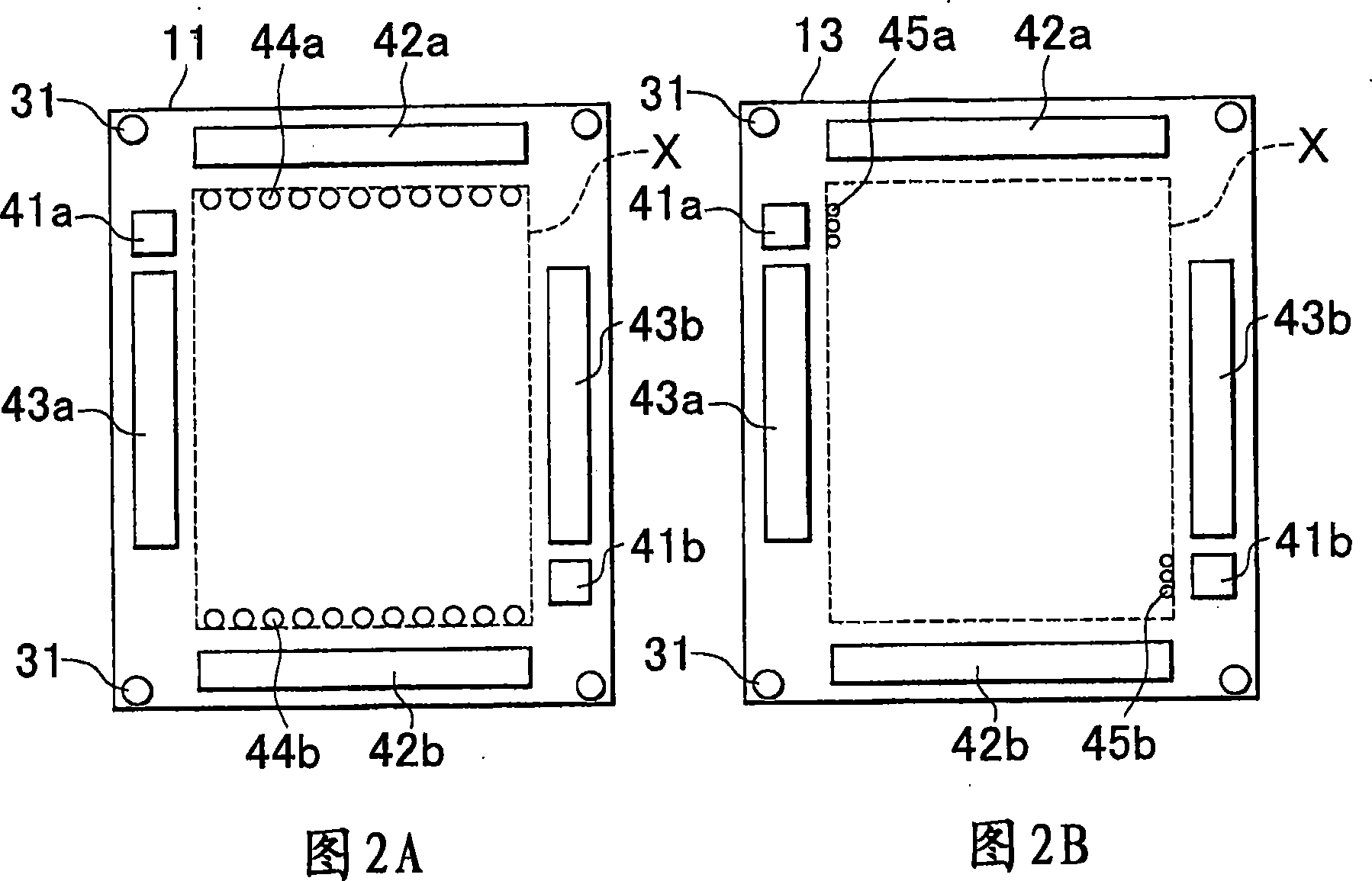
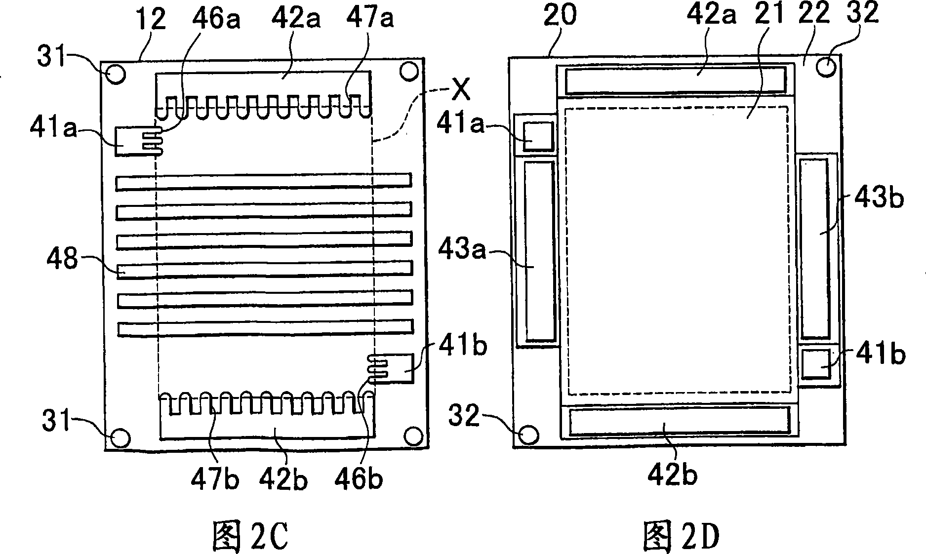
[0018] FIG. 1 is a view schematically showing a fuel cell 100 according to a first embodiment of the present invention. As shown in FIG. 1, the fuel cell 100 has a structure in which separators 10 and gasket-combined membrane electrode assemblies 20 are stacked alternately on top of each other. Each separator 10 has a structure in which an intermediate plate 12 is sandwiched between a cathode-facing plate 11 and an anode-facing plate 13 . These three plates 11 , 12 and 13 forming the separator 10 can be fitted to each other, for example by thermocompression.

[0019] Each gasket-combined membrane electrode assembly 20 includes a membrane electrode assembly (MEA) 21 and a gasket part 22 . The membrane electrode assembly 21 includes: a power generation part 24, in which a catalyst layer is formed on each face of an electrolyte membrane h...


PUM


Abstract

A fuel cell is formed by alternately stacking separators and sealing gasket-combined membrane electrode assemblies. Each sealing gasket-combined membrane electrode assembly includes a membrane electrode assembly and a sealing gasket portion. One of the sealing gasket portion and the separator has a protrusion formed on each face and extending in a stacked direction in which the separators and the sealling gasket-combined membrane electrode assemblies are stacked. The other of the sealing gasket portion and the separator has a recess in which the protrusion is fitted. The protrusions formed respectively on opposed faces of the successive sealing gasket-combined membrane electrode assemblies or the successive separators are located at different positions.

Description

technical field [0001] The invention relates to a fuel cell. Background technique [0002] Fuel cells typically use hydrogen and oxygen as fuels to generate electrical power. Fuel cells have been widely developed as future energy supply systems due to their environmental friendliness and energy efficiency. Some fuel cells have a stack structure in which a plurality of membrane electrode assemblies combined with respective gaskets (hereinafter, simply referred to as “gasket-combined membrane electrode assemblies”) and a plurality of separators are stacked alternately on top of each other . In order to prevent gas leakage, etc., the gasket-combined membrane electrode assembly and the separator need to be properly aligned with each other when stacked. [0003] For example, Japanese Patent Application Publication No. 2002-50368 (JP-A-2002-50368) describes a technique in which a packing member is fitted to a separator to bond the separator and the packing member to each other....

Claims


Application Information

Patent Timeline
Patent Type & Authority Applications(China)
IPC IPC(8): H01M8/24
CPCH01M8/0273H01M8/0206H01M8/0267H01M8/0247Y02E60/521H01M8/242H01M8/1004H01M8/0276Y02E60/50H01M8/2483
Inventor 八神裕一竹下直宏白川努壶阪健二吉川大雄
Owner TOYOTA JIDOSHA KK
Features
  • R&D
  • Intellectual Property
  • Life Sciences
  • Materials
  • Tech Scout
  • Unparalleled Data Quality
  • Higher Quality Content
  • 60% Fewer Hallucinations
Learn More