Fuel injection device, fuel injection system, and method for determining malfunction of the same

A technology of fuel injection device and fuel injection valve, which is applied in the direction of fuel injection device, fuel injection control, charging system, etc., can solve the problems of inability to obtain and difficult to control the injection state with high precision.

Inactive Publication Date: 2013-08-14
DENSO CORP
View PDF1 Cites 0 Cited by
  • Summary
  • Abstract
  • Description
  • Claims
  • Application Information

AI Technical Summary

Problems solved by technology

Therefore, the injection state other than the injection amount Q cannot be obtained as an individual difference
Therefore, it is difficult to control the injection state other than the injection quantity Q with high precision

Method used


Image

  • Fuel injection device, fuel injection system, and method for determining malfunction of the same
  • Fuel injection device, fuel injection system, and method for determining malfunction of the same
  • Fuel injection device, fuel injection system, and method for determining malfunction of the same

Examples


no. 1 example

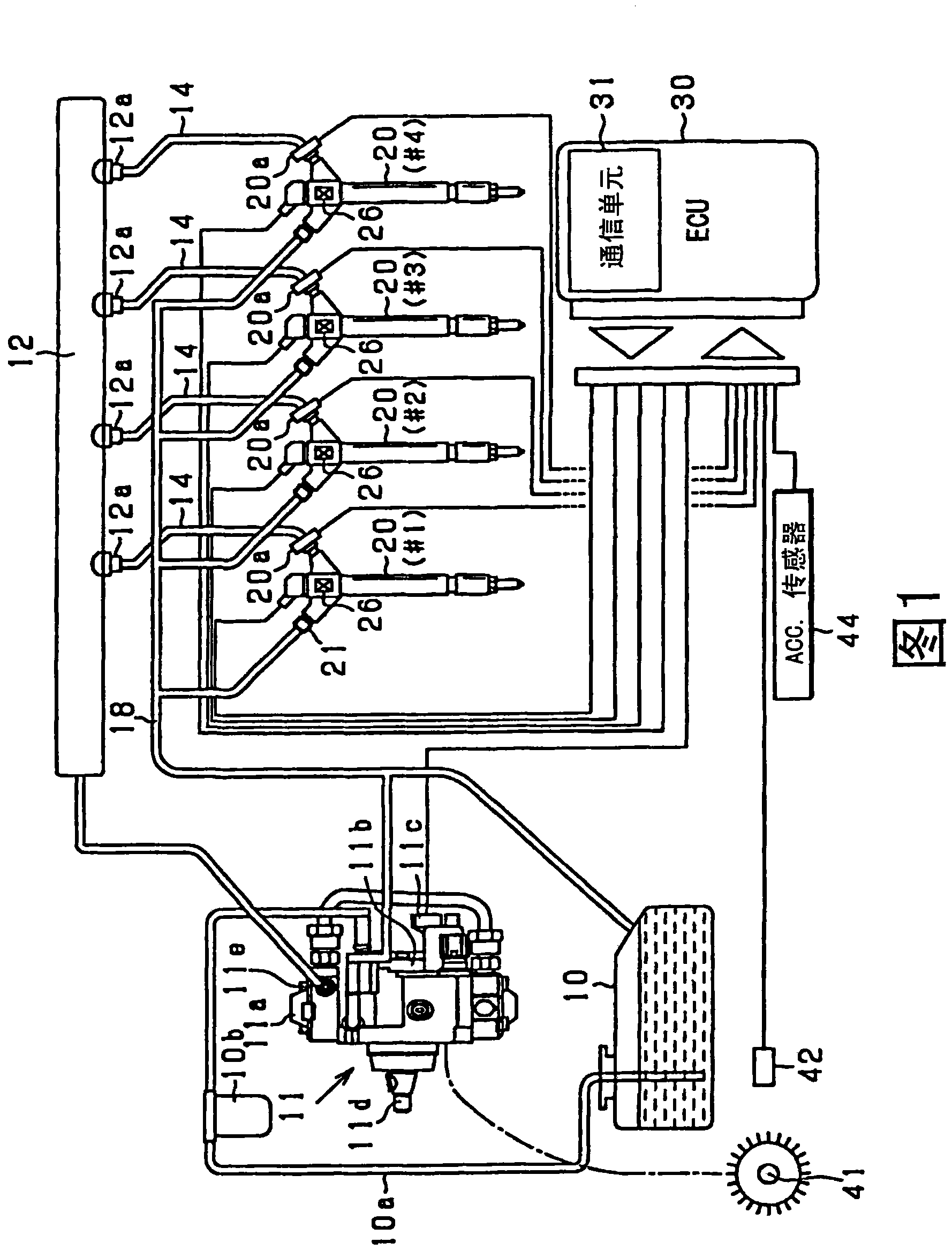
[0029] The fuel injection device according to the present embodiment is installed in, for example, a common rail fuel injection system for an internal combustion engine of an automobile. For example, the fuel injection device is used to inject high-pressure fuel directly into a combustion chamber in a cylinder of a diesel engine. For example, the high-pressure fuel is light oil with an injection pressure higher than 100 MPa.

[0030] First, refer to figure 1 A common rail fuel injection system as an engine system in an automobile according to the present embodiment will be described. In this embodiment, the engine is, for example, an inline four-cylinder engine. Specifically, the engine may be a four-stroke reciprocating diesel engine. In this engine, electromagnetic pickups are provided as cylinder detection sensors for camshafts of intake valves and discharge valves to continuously judge a target cylinder at that time. Each of the four cylinders #1 to #4 repeats a four-s...

no. 2 example

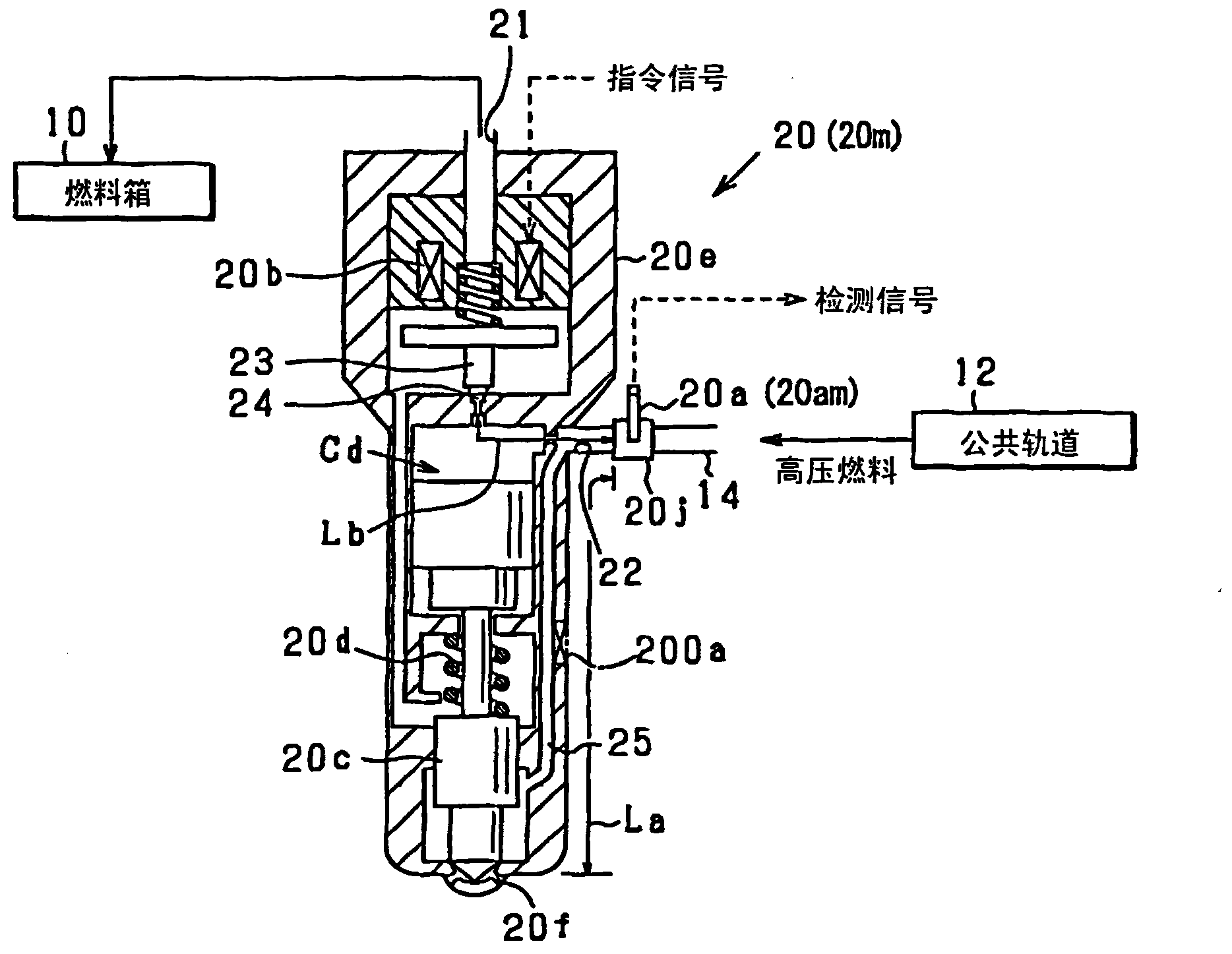
[0112] In the present embodiment, a main injector 20m and a main sensor 20am are prepared, which are different from the injector 20 and the pressure sensor 20a which are objects of inspection. The main injector 20m and the main sensor 20am correspond to a main device. The characteristics of the master device are measured by inspection in advance to obtain reference characteristics as a reference time period. The error of each characteristic of the injector 20 and the pressure sensor 20a with respect to the reference characteristic is measured. The measured error as individual difference information is stored in the IC memory 26 as a storage unit. The injector 20 and the pressure sensor 20a respectively correspond to devices to be inspected.

[0113] The design structure of the main injector 20m is the same as the design structure of the injector 20 which is the test object. The designed position of the pressure sensor with respect to the main injector 20m is also the same a...

no. 3 example

[0121] In this embodiment, in addition to creating the injection control map described in the second embodiment, a failure of the device under inspection is detected.

[0122] Utilized by the measurement operator Figure 4 The measuring instrument 53 shown carries out the processes associated with this fault detection. Figure 14 The fault detection process is shown. This process may be performed at the manufacturing plant, in a state where the injector 20 is mounted together with the pressure sensor 20a, before the injector 20 is shipped. Alternatively, the process can be performed, for example, at a service factory where various maintenance work and inspections are carried out after the injector 20 has been shipped to the market.

[0123] First, at M10 as the first measurement procedure, the command-injection time delay Tnom of the main injector 20m installed together with the main sensor 20am as the main device is measured as the reference invalid time period. The comman...


PUM


Abstract

A fuel injection device includes a fuel injection valve (20) for injecting fuel which is distributed from a pressure-accumulation vessel (12). A pressure sensor (20a) is located in a fuel passage (25), which extends from the pressure-accumulation vessel (12) to a nozzle hole (20f). The pressure sensor (20a) is located closer to the nozzle hole (20f) than the pressure-accumulation vessel (12). A storage unit (26) stores individual difference information obtained by an examination. The individual difference information indicates an injection characteristic of the fuel injection valve (20) and indicates at least one of an injection response time delay (T1) between an injection start point (R3) and a time point (P3), at which a fluctuation is caused by the start of fuel injection in detected pressure of the pressure sensor (20a), and a parameter (La, K, deltaT10) for calculating the injection response time delay (T1).

Description

technical field [0001] The invention relates to a fuel injection device having a fuel injection valve for injecting fuel which is dispensed from a pressure accumulator container. The invention also relates to a fuel injection system with such a fuel injection device. The invention also relates to a method of judging a malfunction in the fuel injection device. Background technique [0002] Conventionally, a common rail fuel injection device includes a common rail as an accumulator container configured to accumulate fuel at a high pressure. The common rail is further configured to distribute high-pressure fuel to the respective fuel injection valves to respectively inject the distributed fuel to cylinders of the internal combustion engine. Such a conventional common rail fuel injection device in JP-A-2006-200378 includes a pressure sensor as a rail pressure sensor. The pressure sensor is mounted to the common rail to detect the pressure of fuel accumulated in the common rai...

Claims


Application Information

Patent Timeline
Patent Type & Authority Patents(China)
IPC IPC(8): F02D41/40F02M47/02F02D41/04
Inventor 中田谦一郎石塚康治
Owner DENSO CORP
Why Eureka
Try Eureka