Brake device and drawer device

A braking device and drawer technology, which can be used in drawers, furniture parts, household appliances, etc., and can solve the problem that the sliding frame does not catch the drive bolt

Inactive Publication Date: 2009-03-18
NIFCO INC
View PDF1 Cites 2 Cited by
  • Summary
  • Abstract
  • Description
  • Claims
  • Application Information

AI Technical Summary

Problems solved by technology

[0003] However, in the device described in the above-mentioned Patent Document 1, in order for the sliding frame to catch the drive pin at the predetermined push-in position of the drawer, both positions must be accurately aligned during installation.
In addition, even if the alignment is performed accurately, the carriage may not catch the drive pin at the prescribed push-in position due to the difference in the load of the drawer and the position of the drive pin dropping.

Method used


Image

  • Brake device and drawer device
  • Brake device and drawer device
  • Brake device and drawer device

Examples


Embodiment Construction

[0038] Refer to Figure 1- Figure 10 The best mode for carrying out the present invention will be described.

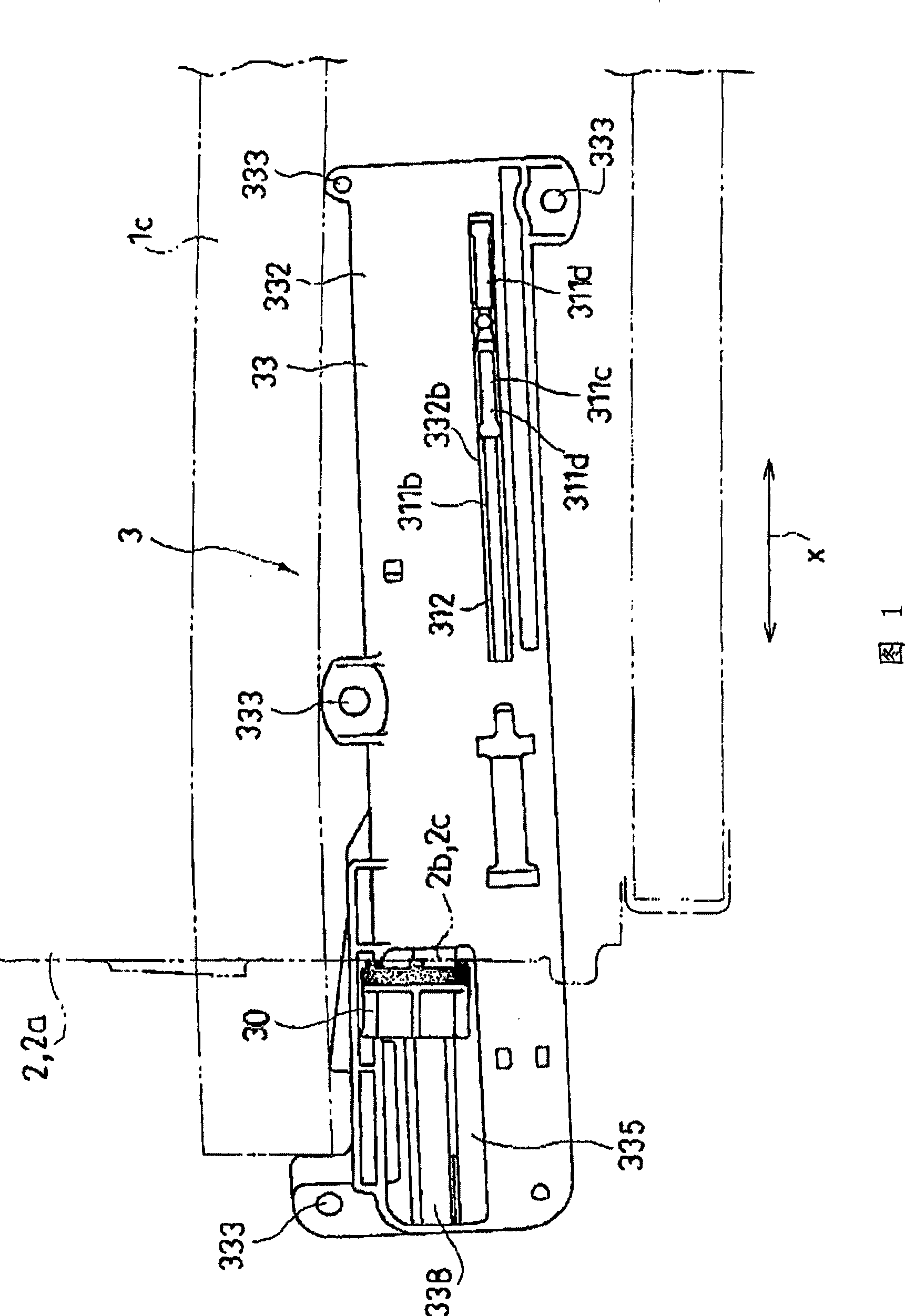
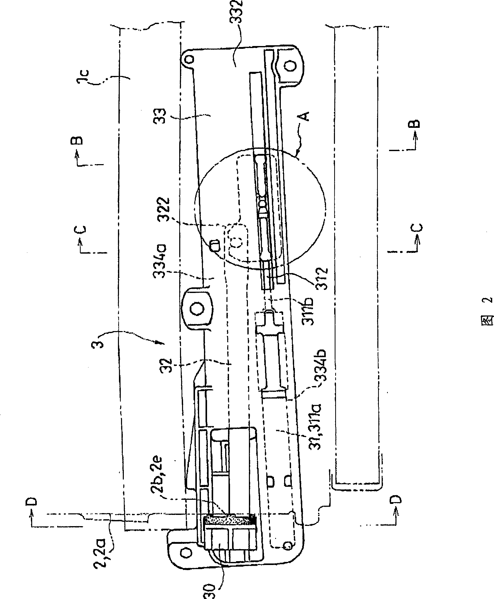
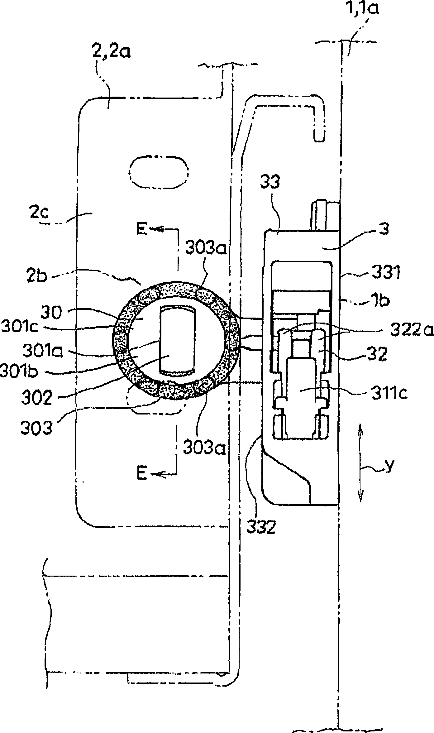
[0039] Here, Figure 1~ image 3 The main parts of the drawer device with the braking device 3 according to the present embodiment are shown respectively, and Fig. 1 shows the state after the inner end 2b of the drawer 2a abuts against the abutting body 30 of the braking device 3 in the standby position [or The state before the abutting body 30 adsorbed on the inner end 2b moves away from the inner end 2b as the drawer 2a moves again (pull-out operation), Fig. 2 shows that the drawer is completely pushed into the drawer from the state of Fig. 1 2a state, image 3 It shows the state of this braking device 3 seen from the front. Figure 4~ Figure 10 The above-mentioned braking device 3 is shown respectively.

[0040] The brake device 3 according to the present embodiment is a brake device that slows down the movement of various movable bodies 2 movably supported by th...


PUM


Abstract

The invention provides a brake device (3) of a movable body (2) which can be arranged without strict position aligning, and a drawer device with the brake device (3). The brake device (3) comprises a butt joint body (30) which butts against a butted joint part (2c) arranged on the movable body (2) at set reciprocating position of the movable body (2) and moves along with reciprocating motion of the butted movable body (2); a damper component (31) which provides braking force to a damper moving part (312); and a connecting body (32) which moves along with the butt joint body (30) and sets the damper moving part (312) in motion. The brake device utilizes magnetic force to absorb the butted joint part (2c) and the butt joint body (30) together.

Description

technical field [0001] The present invention relates to an improvement of a brake device and a drawer using the brake device, which slows down the movement of various movable bodies movably supported on a fixed body from their predetermined forward positions. Background technique [0002] As described in Patent Document 1, when the drawer is closed and the drawer rail moves backward, the drawer is completely pushed in by the sliding frame that catches the driving pin on the side of the drawer and moves backward due to the force of the elastic body. , and a braking force is applied to the movement of the carriage by the fluid damping device. [0003] However, in the device described in the above-mentioned Patent Document 1, in order for the sliding frame to catch the drive pin at the predetermined insertion position of the drawer, it is necessary to accurately align the two during installation. In addition, even if the position alignment is performed accurately, the carriage...

Claims


Application Information

Patent Timeline
Patent Type & Authority Applications(China)
IPC IPC(8): A47B88/04
Inventor 穴泽信宽木村元彦
Owner NIFCO INC
Why Eureka
Try Eureka