Translational rotor type compressor

A rotor-type compressor technology, applied in the field of compressors, can solve the problems of unreliable sealing between sliding vanes and rolling pistons, and achieve the effects of small friction and wear, elimination of voiding, and good sealing effect

Inactive Publication Date: 2011-06-29
ZHEJIANG HONGYOU AIR COMPRESSOR MFG +1
View PDF0 Cites 5 Cited by
  • Summary
  • Abstract
  • Description
  • Claims
  • Application Information

AI Technical Summary

Problems solved by technology

The defect of the above-mentioned rolling piston compressor is that the rolling piston rotates eccentrically. Due to the large radius of rotation, it has a relatively large relative motion speed relative to the end cover, so that large friction and wear will occur; in addition , the sliding plate relies on the return spring to stick to the rolling ring to form a sealing effect. When the speed of the compressor is high, due to the inertial force, such a structure cannot absolutely guarantee that there will be no void phenomenon, and the seal here is a line contact Sealing, the above reasons lead to unreliable sealing between the sliding plate and the rolling piston

Method used


Image

  • Translational rotor type compressor
  • Translational rotor type compressor
  • Translational rotor type compressor

Examples


Embodiment Construction

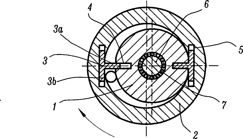
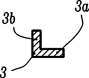
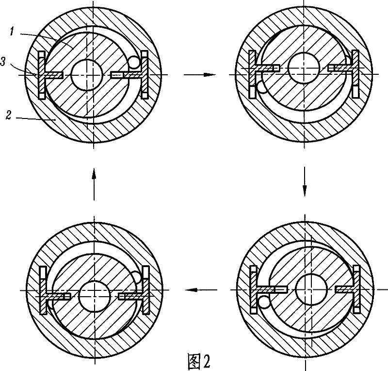
[0009] figure 1 and Fig. 2 respectively show a structural cross-sectional schematic diagram and a schematic working principle schematic diagram of a translational rotor compressor according to the present invention. The compressor includes a rotor 1, a cylinder body 2, and a sliding vane 3, as well as two front and rear end covers (not shown in the figure); the rotor 1 has a cylindrical outer surface, and the rotor 1 has a flat The rotor chute 4 (the best case is to open along the radial direction of the rotor 1); the cylinder block 2 has a round hole-shaped cylinder hole, and the cylinder block 2 is provided with a flat cylinder block chute 5; The slide 3 is a T-shaped structure (such as figure 1 and shown in Figure 2), it consists of two mutually perpendicular flat bodies: a radial flat body 3a and a tangential flat body 3b, wherein the radial flat body 3a is fitted in the rotor chute 4 and is slidably fitted with it, The tangential flat body 3b is fitted in the cylinder c...


PUM


Abstract

The invention relates to a translational rotor compressor, which comprises a rotor 1, a cylinder body 2, a sliding blade 3 and an end cover, and is characterized in that a flat rotor chute 4 is arranged on the rotor 1; a flat cylinder body chute 5 is arranged on the cylinder body 2; and the sliding blade 3 has a T-shaped structure or an L-shaped structure, and consists of a radial bluff body 3a and a tangent bluff body 3b which are perpendicular to each other, wherein the radial bluff body 3a is arranged inside the rotor chute 4 and is matched with the rotor chute 4 in a sliding way, and the tangent bluff body 3b is arranged inside the cylinder body chute 5 and is matched with the tangent bluff body 3b in a sliding way. The rotor 1 is limited by the sliding blade 3 and only performs translational rotation, and the swinging radius of each mass point on the rotor 1 is equal to the eccentric distance of the rotor 1 opposite to a cylinder hole on the cylinder body 2; and because the valueof the eccentric distance is small, the relative kinematic velocity of the rotor 1 relative to the end cover and the cylinder body 2 is small as well, namely the friction and the abrasion between therotor 1 and the end cover and between the rotor 1 and the cylinder body 2 are small. Moreover, the sliding blade 3 and the rotor 1 always adopt the means of surface contact, so that the sealing reliability of the translational rotor compressor is higher than that of line contact.

Description

technical field [0001] The present invention relates to the field of compressors, in particular to a rotary compressor, and more specifically to a translational rotary compressor. Background technique [0002] As we all know, the rolling piston compressor has many advantages such as small size, light weight and simple structure, so it is widely used in the fields of refrigeration, air conditioning and air compression. It includes cylinder body, sliding vane, return spring, end cover and a ring The rolling piston of the compressor is provided with a flat slide groove on the cylinder block of the compressor, and the slide plate is arranged in the slide groove and slidably fit with it. The rolling piston is also called the rotor, and it is set on an eccentric curved neck. Driven by the eccentric curved neck, the rolling piston rotates; the cylinder body has a circular hole, and the outer circular surface of the rolling piston is in contact with the cylinder hole; the outer end ...

Claims


Application Information

Patent Timeline
Patent Type & Authority Patents(China)
IPC IPC(8): F04C18/34
Inventor 陈君立阮勤江耿爱农李辛沫
Owner ZHEJIANG HONGYOU AIR COMPRESSOR MFG
Why Eureka
Try Eureka