Wireless communication system and method

A wireless communication system and information transmission technology are applied in the field of wireless communication systems to achieve the effect of improving reception characteristics

Inactive Publication Date: 2009-03-18
NEC CORP
View PDF4 Cites 12 Cited by
  • Summary
  • Abstract
  • Description
  • Claims
  • Application Information

AI Technical Summary

Problems solved by technology

This patent document 1 also discloses that when estimating the phase deviation of the channel, a difference method based on the phase difference (relative error) between symbols is used, but it is different from the subject of the present invention described later (the phase fluctuation before and after frequency hopping can be measured). Quantity) is a completely different content

Method used


Image

  • Wireless communication system and method
  • Wireless communication system and method
  • Wireless communication system and method

Examples


Embodiment 1

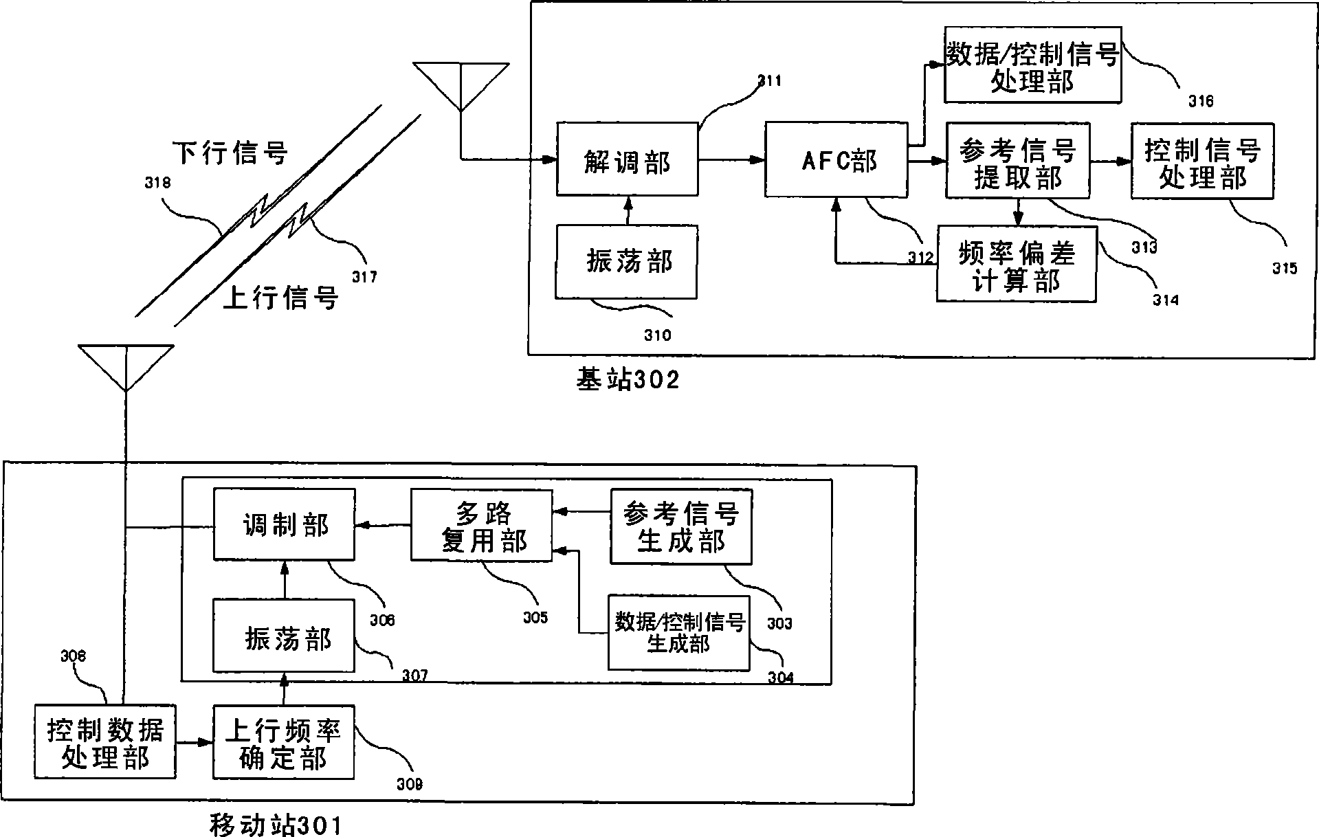
[0043] Embodiments of the present invention will be described with reference to the drawings. image 3 is a diagram showing the main structure of an embodiment of the present invention. image 3 There are a mobile station 301 and a base station 302 for wireless communication. exist image 3 The demodulation unit and the like in the mobile station 301 are not shown in the figure, and the modulation unit and the like in the base station 302 are also not shown. Also, for simplicity image 3 Only one mobile station 301 is shown.

[0044]The mobile station 301 has: a reference signal (Reference Signal) generation unit 303, a data / control signal (Data / Control Signal) generation unit 304, a multiplexing unit 305, a modulation unit 306, an oscillation unit 307, a control / data (Control / Control Signal) Data) processing unit 308 and uplink frequency determination unit 309 .

[0045] The base station 302 has: a demodulation unit 311, an oscillation unit 310, an AFC (Automatic Frequen...

Embodiment 2

[0080] As other embodiments of the present invention, it is also possible to measure the frequency deviations of the control channel in a plurality of time slots, and perform statistical processing on those frequency deviations, such as averaged or smoothed values, to calculate the frequency of the received baseband signal fix.

[0081] If the bit (bit) length of the reference signal is short, or the interval of the reference signal cannot be ensured, and the accuracy of the measurement value of one time slot cannot be ensured sufficiently, it can be obtained by averaging or smoothing the measurement values ​​of multiple time slots The value is used to determine the frequency deviation to improve the accuracy of frequency correction.

Embodiment 3

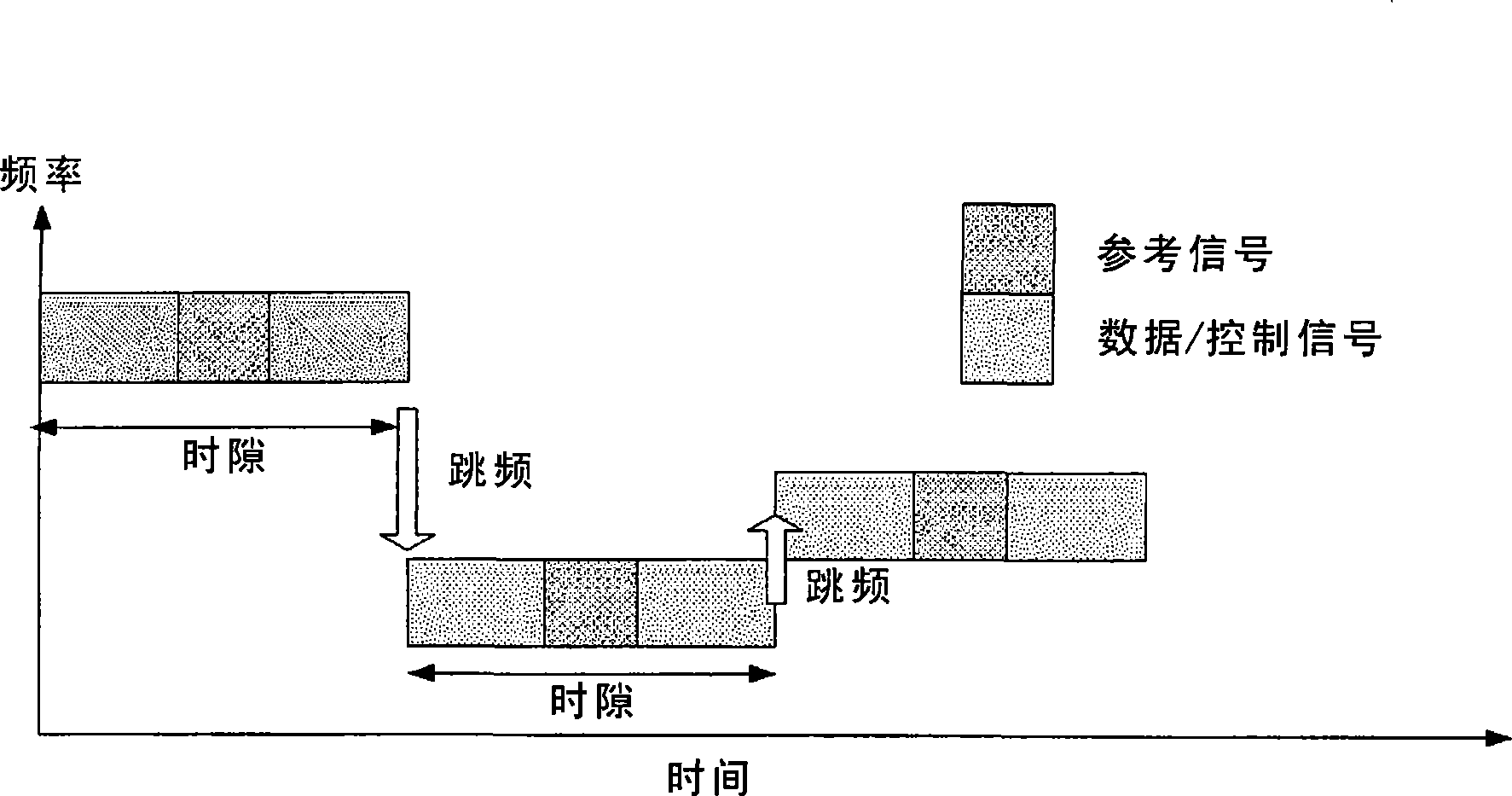
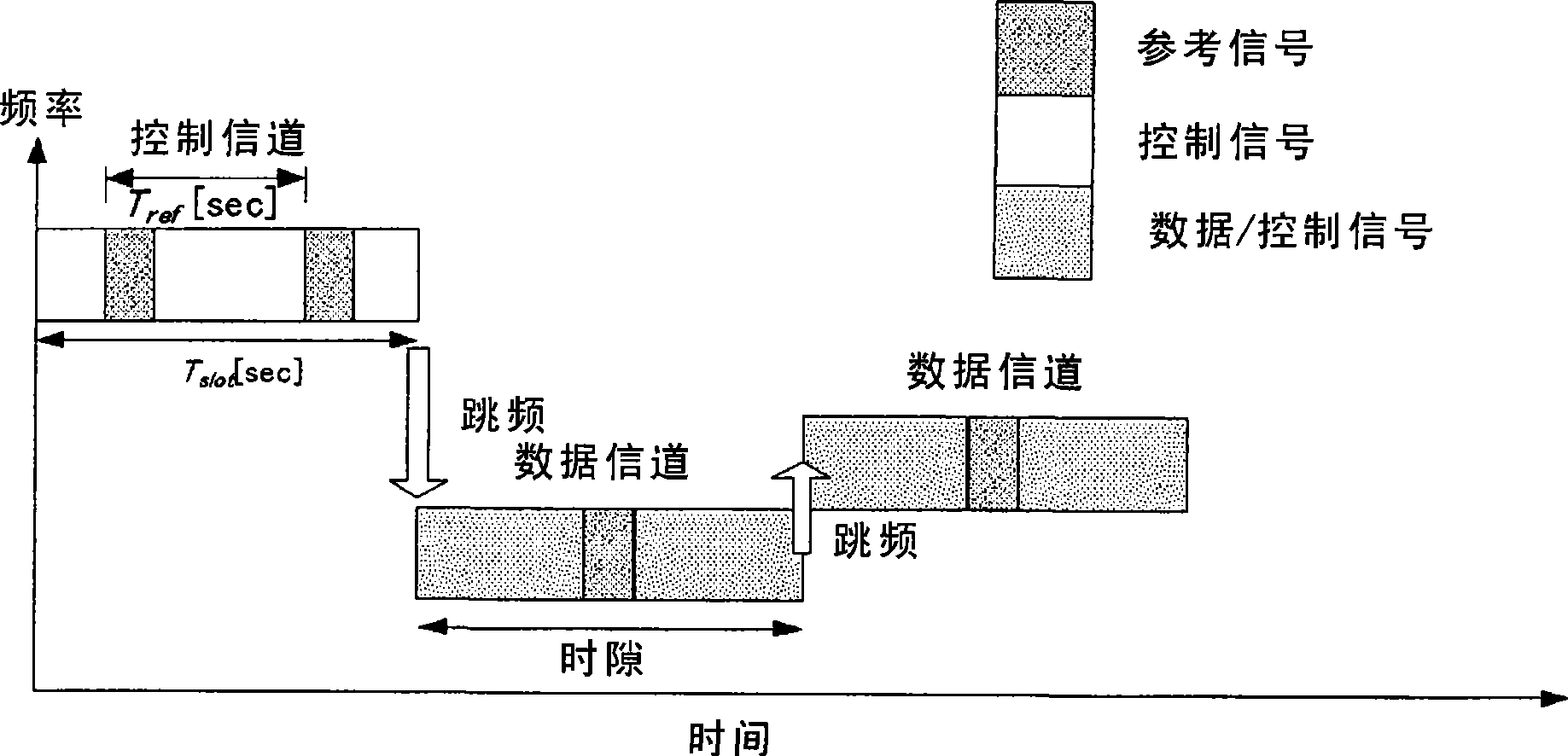
[0083] For example, in the data channel, when there are multiple time slots staying at the same frequency, or when the frequency hopping cycle is set to more than 2 time slots briefly, the phase obtained in the data channel can be used only during this period The difference information (phase fluctuation amount) is used to correct the frequency deviation. That is, in figure 2 In the shown example of the time slot format, there is one reference signal for each time slot. At this time, multiple reference signals of data channels with more than two time slots can be used to obtain Δφ according to the method in Embodiment 1 ref , Find the frequency deviation Δf.


PUM


Abstract

Provided are a wireless communication system and a method for enabling measurement of amount of phase fluctuation before and after frequency hopping and improving the reception characteristic. A mobile station (301) transmits a plurality of reference signals upon placing the reference signals in temporally spaced-apart relation in at least one of information transmission units (one or a plurality of time slots) wirelessly transmitted in conformity with a hopping period, and a base station (302) receives an information transmission unit that has been transmitted from the mobile station (301) and, if this information transmission unit is one that includes a plurality of the reference signals, obtains a phase fluctuation from the plurality of reference signals and obtains a frequency deviation from the phase fluctuation.

Description

technical field [0001] The present invention relates to a wireless communication system, in particular to a system and method for wireless communication in a frequency hopping manner. Background technique [0002] In a mobile communication system that performs wireless communication using a frequency hopping method, frequency conversion of a transmission carrier is performed corresponding to a time slot as a unit of information transmission. The reception function on the base station side can be improved by correcting the deviation between the transmission carrier frequency transmitted from the mobile station and the reception carrier frequency received by the base station. [0003] For example, when the frequency deviation between the mobile station and the base station is 1 kHz, and the time slot (Time Slot) length is 0.5 ms, the phase of the received baseband signal is flipped by 180° (0.5 ms X 1 Hz X 360°) within one time slot. [0004] Therefore, when determining the p...

Claims


Application Information

Patent Timeline
Patent Type & Authority Applications(China)
IPC IPC(8): H04B7/26H04B1/707H04B1/713H03J7/00H04B1/3822H04B1/40H04B1/7156
CPCH04L2027/0026H04L2027/0065H04B1/713H04L2027/0093H04L27/0014H04L27/16H04L27/18
Inventor 河端尚岩崎玄弥友清亮
Owner NEC CORP
Why Eureka
Try Eureka